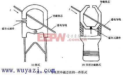
In modern engineering technology, it is often necessary to measure DC current, sometimes DC current value is higher than lOkA. In the past, resistor shunting method was used to measure such a large current. This method has many disadvantages, such as the complicated structure of the shunt, heavy weight, power consumption, and copper consumption. Using the principle of the Liner effect to address large currents can overcome some of the above shortcomings. The erbium effect galvanometer has a simple structure, low cost and high accuracy. It is largely independent of frequency and is convenient for long-distance measurement. It is not necessary to disconnect the circuit when measuring. The use of the Hall element side current is achieved by detecting the magnetic field around the energized conductor through the Hall element. The following describes a method for measuring a large current using a Liner component. 1) Wire bypass method This method is the simplest method of placing the Hall element in the vicinity of the energized wire, passing a constant current to the Hall element, and using the Hall element to measure the magnetic field generated by the measured current. It is possible to determine the measured current value from the Hall voltage output from the component. As shown below. Although this method is simple in structure, its accuracy is poor, and it is subject to external interference. It is only applicable to some unimportant occasions. 2) Wire-through magnetic core method If the core of the magnetic conductor is made of ferromagnetic material, the electric conductor to be tested is passed through the center of the magnetic conductor, and the phase element or the integrated sensor is placed in the air gap of the magnetic conductor. The magnetic lines of force can be concentrated by the toroidal core. See Figure 8-34. When there is current flowing in the wire, a magnetic field is generated around the wire, and the core of the magnetizer is transformed into a temporary magnet. A magnetic field is formed in the annular air gap. The greater the current in the conductor, the greater the magnetic induction at the breath. The Hall voltage Vr output from the Hall component is larger. Therefore, we can detect the current in the wire through the Hall voltage. This method can improve the accuracy of current measurement. In practical applications, for the convenience of measurement, the magnetic core of the magnet may be formed into a clamp shape or a shape of a non-closed magnetic circuit, as shown in the following figure. 3) Core winding method This method is shown in Figure 8-36. It is a combination of a standard toroidal core and a SL350M Hall linear integrated sensor. The measured energized wire is wound around the core of the conducting magnet, and a magnetic induction of 0.0056 T is generated at an air gap every 1 ampere. If the maximum range is 0-20A, the wire will be wound to 9 turns to produce a magnetic induction of about 0.1T, and the SL350M will have a voltage output of 1.4V. Shenzhen Ruidian Technology CO., Ltd , https://www.wisonens.com
