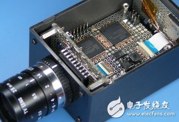
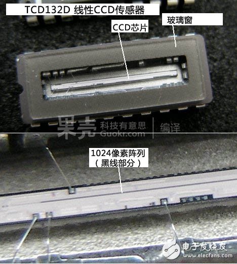
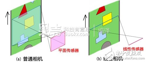
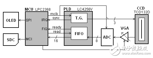
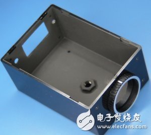
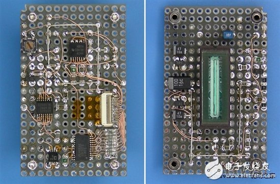
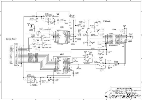
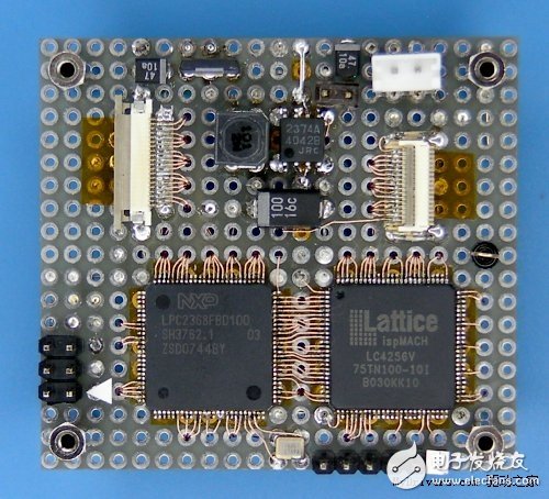
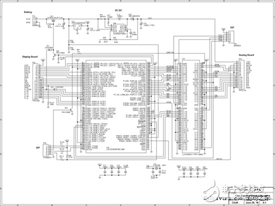
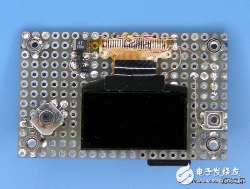
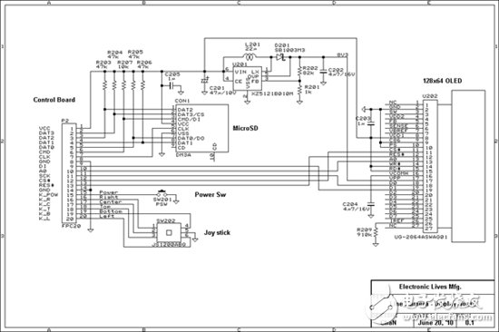
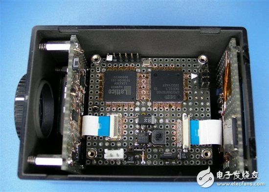
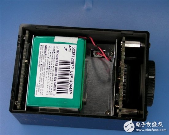
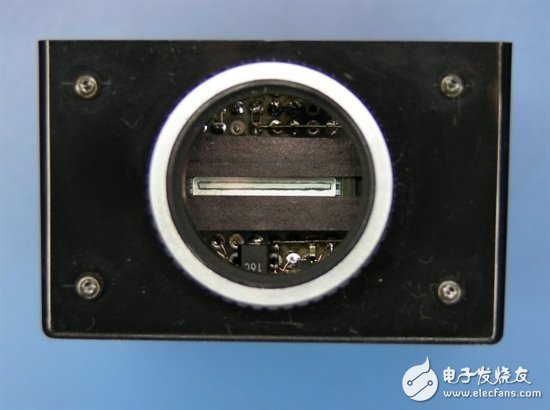
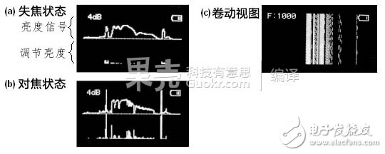
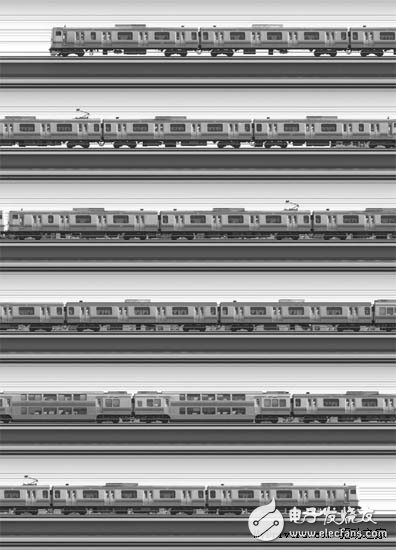
A linear scan camera is a type of digital camera. Such cameras generally function as components in various machines and are generally not easily seen in real life. This production can help you DIY and learn more about linear scanning cameras. A linear CCD sensor (Charge-coupled Device line sensor) is the most important part of a linear scanning camera. I bought it in Electronic City more than a decade ago. However, it is difficult to make a small-volume portable linear scanning camera. The circuit part requires a high-performance microprocessor and a large-capacity memory. At that time, the general personal production can only respect these expensive high-end goods. So it was thrown into a broken box by me, and I almost forgot it. After ten years, thanks to the fast-growing semiconductor industry, the price of chips has finally fallen to an acceptable level. Now even beginners are free to enjoy 32-bit microprocessors and massive memory cards, so I started the project with the latest technology! 1, linear scanning camera 1.1, camera principle Comparison of ordinary flat cameras and linear cameras A linear scan camera is a type of digital camera that uses a linear CCD sensor (one-dimensional CCD device) as an image sensor. A conventional digital camera captures an image on a focal plane with a planar CCD device (two-dimensional CCD device), and the acquired pattern is a two-dimensional plane. For a linear scan camera, the pattern it acquires is a one-dimensional line! Even if the image obtained each time has only one line, the linear scan camera still has the ability to obtain a complete image. When making a linear scan camera, you need to constantly move the camera or the subject - so that each part of the data obtained is stored in the memory, and finally piece together into a complete image like a woven fabric. In the past film era there was a slit camera. Similar to the linear scanning camera here, it is imaged by a narrow slit (one-dimensional window), and a one-dimensional image is combined to obtain a complete two-dimensional image. 1.2, functional applications Linear scan cameras have these features: - High resolution. Even cheap sensors can achieve resolutions above 10,000 points. - Simple and compact optical system. No need to scan the table. - There is no limit to the size and length of the object, and it can be correctly imaged for very long objects. Thanks to these features, linear scan cameras are widely used in many places and you can find them on many important devices. such as: - photocopier - Image scanner - fax machine - Machine vision (checking long objects) - Satellites (such as those who took google maps) - End point photography (sports competition) 2, hardware composition 2.1, function module The figure above shows the various functional modules that make up the linear scan camera. The linear CCD sensor passes the collected light sensing information to an AD (Analog-to-Digital) converter for digitization, and then inputs the controller as a digital signal. These data can be displayed on the display or transferred to memory. The frequency of scanning is adjustable from 500 lines per second to 2000 lines per second, depending on the type of CCD device. The circuit portion is divided into three major parts, each connected by a flexible printed circuit cable. I often don't use custom PCBs because they are too expensive and don't have DIY spirit, design troubles, and it's troublesome to change later. This one-off production works best on the hole board camera. What kind of flying line skill is this... 2.2, light path and outer casing The picture above shows how to make a shell for this linear scan camera. This is a casing modified from a SW-85B plastic box from Takachi Electric Industrial. The light path of this project needs to be controlled very accurately, so special attention must be paid to the design, processing and assembly. Here are the drawings of the outer casing. The analog part of the board with linear sensor is mounted on a movable screw so that the distance can be adjusted at will. The lens used this time is a C-mount ring, which is one of the standard lenses used in industrial cameras, but not so good. I used a C-CS adapter ring to mount the lens to the housing. A UNC (Inch Unified Thread Series) nut is attached to the underside of the box to secure the camera. A conductive coating is applied inside the box for electromagnetic shielding. 2.3, analog circuit part The picture above shows the analog circuit part of this production, which contains the most important devices in a linear scan camera. A CCD linear sensor and analog circuit are mounted above. The CCD linear sensor is a Toshiba TCD132D monochrome CCD that is sensitive to infrared light, so an infrared filter (IRCF) is required to obtain an image that is similar to the human eye. The CCD linear sensor requires a clock signal drive from the main control board. The sensor's analog image signal output is first passed through a variable gain amplifier (AD8830), which is then converted to a digital signal by an analog-to-digital converter (ADC1173). The 8-bit digital signal output of the ADC1173 is sent to the main control board. The pixel acquisition rate is variable from 0.5 MHz to 2 MHz, but the analog to digital converter must be operating at a clock frequency of at least twice the sampling rate. After every two samples, a digital signal is output to the main control board. This is a circuit diagram of the analog circuit section. 2.4, the main control circuit part The main control board includes a microprocessor (MCU), a programmable logic device (PLD) and a power supply section. The microprocessor chip is an NXP LPC2368 that integrates an ARM7TDMI core operating at 72 MHz, 32K+16K+8K bytes of SRAM in 512K bytes, and a powerful peripheral. It can control an external MicroSD memory card in 4-bit native mode via an integrated SD card controller. The LPC series of ARM microprocessors are widely used in today's electronic production, because its market policy is very right, inexpensive. A programmable logic device (LC4256V) is used to drive the CCD linear sensor. A clock generator for clocking the sensor and a first-in first-out queue are configured in the PLD. The power supply section provides digital power (3.3V). And the analog part of the power supply (12V). This is the circuit diagram of the main control circuit. 2.5, display circuit part The display part of the circuit is mounted on the back of the box, which provides the camera's operator interface. The above device includes an OLED display, switch. Five-way keys and a MicroSD slot. Open the cover to install or remove the SD card. This is a circuit diagram of the display circuit section. Inside view Bottom view Lens interface view 3, software composition 3.1, data processing The AD converter's pixel acquisition rate can be as high as 2.1M pixels per second. First, the image data is stored in the buffer memory of the microprocessor. Because the amount of data per second of 2.1M is too much for the software, the image data is stored in the PLD's FIFO queue. When the queue is half full, it triggers the DRDT interrupt of the microprocessor, and then the microprocessor accepts half of the queue data at a time. The size of the queue is 16 bytes, which means that the software's operating cycle is sufficient as long as 1/8 of the pixel acquisition rate is available. This is not too fast for triggering an interrupt, but it still requires the microprocessor to run at high speed. This project uses the ARM7TDMI core's fast interrupt request function (FIQ, fast interrpt request, which generates low-latency interrupts through grouping registers), but this feature has been removed in the Cortex-M3 core. When the microprocessor responds to the FIQ request, some registers are switched to the FIQ's grouped register state, and then the FIQ routine can be directly entered/exited without the switching process being eliminated. To maximize execution efficiency, FIQ routines are generally written in assembly language. In the data waveform diagram with this function enabled, it can be observed that 8-bit data only needs 0.8 microseconds when it is not stored, and it takes only 2 microseconds to write the SD card from the bus in DMA mode. The delay is acceptable. There are 1094 pixels in each row of data, but only 1024 of them are valid. The data is stored in the memory, and the interrupt signal SYNC# is output at the beginning of each line of data to synchronize the data of the first pixel. 3.2, reconstructed image The captured data can be stored in a MicroSD card in a common 8-bit grayscale BMP bitmap format, 1024 pixels wide, depending on the long-term shooting time. The format of the storage is DCIMLCAMYnnnn.BMP (nnnn is the number), which is almost the same as a normal digital camera. There are some difficulties in using an inexpensive microprocessor to store image data in an SD card, mainly because the input data is stored in a file in a very short time. The maximum data transfer rate in this production is 2MB per second. Fortunately, the LPC2368 has an MCI (SD/MMC card native control mode) that provides 8MB/s data read and 6MB/s data write capability. But this refers to the average speed when reading and writing large files. In fact, it takes some dead time between each read and write to be used in the internal processing and file system of the SD card. To avoid these wastes, a data buffer is used. Data is temporarily stored in dead time, but the memory size of the microprocessor system is limited, and there is not necessarily enough space for buffering. Let us estimate the amount of time that can be tolerated each time a data write operation is performed. In this production, all 32K SRAM is used as a data buffer, and the program runs on 16K of ethernet RAM. The data buffer is divided into two halves, one of which fills the data and the other writes the data to the flash. This requires writing 16KB of data every 8 milliseconds, and each operation must be completed before the next operation. The next software trick can solve this problem. The most important delay in data writing occurs during cluster allocation. This is a big problem in real-time operating systems. The dead time caused by cluster allocation can vary up to several seconds depending on the situation. Cluster pre-allocation is used in this production (use the f-lseek function to write a space larger than the current requirement when writing data) to avoid re-positioning the partition table when writing data. Each write operation contains a cluster boundary condition to end the operation. Imagine that the files in the SD card pre-organize a neat space for data, which avoids the unknown problem that causes a lot of delays in the process of writing data. Despite these methods to minimize dead time, SD cards have more or less internal processing time. When selecting an SD card, you need to pick an SD card that writes as fast as possible. I have compared between many brands and found that the Toshiba SD card has the lowest write latency and the most stable performance. 3.3, display image Since the obtained image data is a one-dimensional line, it cannot be displayed like a two-dimensional image of a conventional planar image. Some special display modes are needed for this problem. One of them is the range view, where the input image signal is connected to the Y-axis, just like an oscilloscope's input. The Y-axis signal represents the brightness and the X-axis signal represents the position of each point on the linear sensor. This mode is suitable for viewing sensitivity and focusing. The difference in data between different points can be used to help focus. When the image is focused, many peaks and valleys are generated on the waveform. The largest peak-to-peak value indicates that the focal length is already on. This is the prototype of the autofocus feature in digital cameras today. The other is a scroll view where the image scrolls up and the newly scanned image appears at the bottom of the screen. This mode can be used to adjust the line resolution. The aspect ratio of the resulting two-dimensional image is determined by the line resolution and the speed at which the object moves. The scroll view can show the captured 2D scene, but if the subject does not move, only the horizontal line is left, so one of the camera or object must be shot at the given speed of movement so that you can observe it. Adjust the line resolution on one side. 4, instructions for use The general use of linear scanning cameras is similar to that of film-era slit cameras. The slit camera easily beats the linear scan camera in performance, and its photosensitive particle diameter is 14um, which is much smaller than the diameter of the cell in the CCD, which means excellent resolution. But playing a slit camera means you have enough framing, focusing, shooting and printing capabilities that non-old birds can't. Camera position This camera needs to be fixed at a suitable angle so that the image created by the object can sweep across the linear sensor. For example, if the object moves laterally or if the lateral direction is particularly long, the camera is preferably fixed in a position where the linear sensor is in a vertical position. This angle must be accurate, otherwise the picture taken will have a distortion similar to a parallelogram. Adjust the focus This linear scan camera is controlled by a 5-way joystick (up, down, left, and center), and press to the right to switch the display mode (range mode or scroll mode). First, the level of the input signal can be controlled by aperture or gain (up and down). Gain control can also be adjusted automatically with the left button. Next, adjust the focus through the focus ring until the peak-to-peak value of the signal is maximum. Adjust sensor line resolution The camera can be adjusted to match the sensor line resolution in scroll mode. Adjust until the correct aspect ratio is displayed on the screen. The resolution of the sensor line can also be calculated by the speed at which the object moves, the distance of the object from the lens and the focal length. This is slightly inaccurate, but the digital image can be corrected by post processing. Of course, if the sensor line resolution is too low, this process will lose some information. Generally speaking, the high resolution of the sensor line is not a bad thing, or the sensitivity may be lower. The sensor line resolution affects the exposure time (sensitivity), so the gain of the input level needs to match the different line resolutions. Get image The middle button is used to start/stop shooting. The image can be recorded by pressing the button. The cluster pre-allocation will complete in 0.5 seconds and then pause until it is released. When the button is released, the image recording starts, and then stops when any button is pressed or until the written data reaches the boundary of the cluster pre-allocation area. The pre-allocated size is configured to 100,000 lines (approximately 100 MB), but can vary depending on the size of the subject. The resulting image file can be pre-processed on the computer to adjust the orientation of the image, aspect ratio or gamma correction. 5, real shot effect display Switch & Socket,Sockets And Switches,Brass Plug Sockets,Light Switches And Sockets WENZHOU TENGCAI ELECTRIC CO.,LTD , https://www.tengcaielectric.com