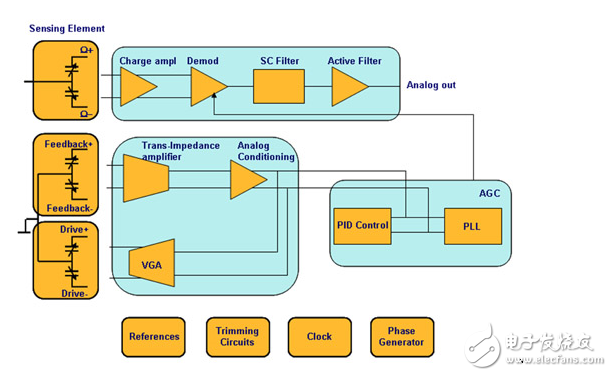
The wave of MEMS sensor market can be from the earliest automotive electronics to consumer electronics in recent years, and the upcoming Internet of Things era. Nowadays, a single sensor can no longer meet people's needs for functionality and intelligence. The integration of sensors such as MEMS inertial sensors, MEMS environmental sensors, MEMS optical sensors, and even biosensors will become a trend for sensor applications in the new era. For a worker to be good at something, he must first sharpen his tools. Here he begins with MEMS gyroscopes and briefly introduces the MEMS gyroscopes, their main performance parameters, and their use. Traditional mechanical gyroscopes mainly use the principle of conservation of angular momentum, that is, for a rotating object, its axis of rotation does not change with the rotation of the support carrying it. MEMS gyroscopes mainly use the Coriolis force (a tangential force that a rotating object receives when it moves in a radial direction). The disclosed micromachined gyroscopes use the concept of angular velocity of a vibration sensor to induce and detect vibrations. Coriolis force. The core of a MEMS gyroscope is a micromachined mechanical unit that is designed to resonate in accordance with a tuning fork mechanism and convert the angular velocity to the displacement of a specific sensing structure through the Coriolis force principle. Take a uniaxial displacement (yaw, YAW) gyroscope as an example, and discuss the simplest working principle through the use of Tully. Two identical masses oscillate in opposite directions, as indicated by the horizontal arrows. When an external angular velocity is applied, a Coriolis force appears. The direction of the force is perpendicular to the mass direction of motion, as indicated by the vertical arrow. The resulting Coriolis force shifts the sense mass, which is proportional to the magnitude of the applied angular rate. Since the moving part of the sensor sensing part (rotor) is located on the side of the fixed electrode (stator), the upper displacement will cause a capacitance change between the stator and the rotor. Therefore, the angular velocity applied to the input part of the gyroscope is The electronic parameter that can be transformed into a special circuit can be detected---capacity. The following figure shows the system architecture of a MEMS gyroscope. The signal conditioning circuit of the gyroscope can be divided into two parts: a motor drive and an accelerometer sensing circuit. Among them, the motor driving part is through the electrostatic induction method, so that the driving circuit vibrates back and forth to provide an excitation for the mechanical element; and the sensing part measures the displacement of the Coriolis force on the sensing quality by measuring the capacitance change. Of course, MEMS gyroscopes also have other functional modules, such as self-test function circuits, low power consumption, and motion wake-up circuits. The following mainly introduces the main performance parameters of MEMS gyroscopes. Range (dynamic range) DYNANMIC RANGE Sensitivity SENSORTIVITY RESOLUTION Zero-angle speed output (zero output) ZERO OUTPUT Inter-axis Intersection Sensitivity INTER AXIS sensiTIvity Scale factor Non-linearity Linear acceleration sensitivity Vibration sensitivity Zero bias stability Noise density Random walk system bandwidth Bias voltage sensitivity Self-test function Power consumption Impact survivability range of working temperature Packaging error The gyroscope's range is usually expressed as the maximum input angular rate in the positive and negative directions, for example: +/-300 degree/sec. The larger the value is, the stronger the gyro's sensitive angular rate is. In this input angular rate range, the nonlinearity of the gyro scale factor can meet the specified requirements. Usually, the gyroscope's range can be configured. Sensitivity (resolution) represents the minimum input angular rate that can be sensed at a specified input angular rate, such as: 0.05 degree/sec/LSB. In general, the larger the measuring range of a MEMS gyroscope, the lower the sensitivity. The scale factor (scale factor) is the ratio of the gyroscope output to the input angular rate. This ratio is represented by a specific straight line slope, which is obtained by least-squares fitting based on input and output data measured over the entire input angular rate range. Non-linearity is the ratio of the maximum deviation and the maximum output of the output of the gyroscope relative to the least-squares fit line in the range of the input angular rate. It represents the degree of deviation of the actual input and output data of the gyroscope, and determines the degree of deviation. The credibility of the combined data. The linear acceleration sensitivity reflects the sensitivity of the gyroscope to acceleration in units of degree/sec/g. Vibration sensitivity refers to the degree of sensitivity of the gyroscope to vibration, and the unit is degree/sec/g2. The less sensitive the gyroscope is to linear acceleration and vibration, the better the performance of the gyroscope and the more effective the algorithm that is built. Zero offset refers to the output of the gyroscope under zero input state. It is expressed as the input angular rate equivalent to the average equivalent of the long time output, that is, the degree of dispersion of the observation around the zero bias, such as 0.005 degree/sec for each Seconds will drift 0.005 degree. The long-term steady-state output in the zero-input state is a stable stochastic process. That is, the steady-state output will fluctuate and fluctuate around the mean (zero bias), and is customarily represented by the mean square error. This mean square error is defined as zero bias. stability. The initial offset error can be understood as a static error, which does not fluctuate over time and can be calibrated using software. When the gyroscope is in the zero-input state, the shed output signal is a superposition of white noise and a slowly varying random function. The diffuse random function can be used to determine the zero bias and zero bias stability indicators. The white noise is defined as the standard deviation of the equivalent rotational angular velocity in square root of the unit detection bandwidth in units of degree/sec/√Hz or degree/hr/√Hz. This white noise can also be represented by the random walk coefficient in units of degree/√Hz. The random walk coefficient refers to the gyro output error coefficient that is accumulated over time by white noise. When the external conditions are basically unchanged, it can be considered that the main statistical characteristics of the various noises analyzed above do not change over time. Bias voltage sensitivity refers to the sensitivity of the output of the gyroscope to changes in the power supply, such as: 0.03degree/sec/V, that is, how much the output angular rate changes for each 1V change in the power supply. Bandwidth is the frequency range over which the gyroscope can accurately measure the angular rate of the input. The larger the range, the stronger the dynamic response of the gyroscope. The self-test function automatically tests the mechanical and CMOS circuit parts of the device before use to provide system robustness. Power consumption includes the power consumption of the gyro when running at different resolutions or different data output rates, and the power consumption at rest. This indicator is particularly important in low-power applications such as wearables, IoT applications, and more. Impact viability refers to the ability of a gyroscope to withstand acceleration shocks in varying degrees. For example, after an acceleration of 2000 g, the gyroscope ensures that the system is working properly. Considering that the application environment of the gyroscope may receive a large impact, this index is particularly important. Generally, the gyroscope will hang up when it exceeds its acceleration tolerance range, and it must be restarted to work normally. The mechanical architecture of the MEMS gyroscope determines that the temperature will affect the output of the data, and exceeding the operating temperature range may cause a large deviation in the data output. The package error is the angle between the diagonal of the die and the diagonal of the package.
Sweet safe packing are available Covered Copper Wire,Film Covered Flat Copper Wire,Non Woven Covered Copper Wire,Polyester Film Covered Copper Wire HENAN HUAYANG ELECTRICAL TECHNOLOGY GROUP CO.,LTD , https://www.huaonwire.com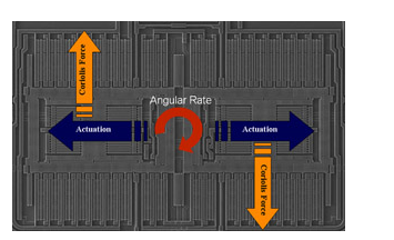
About Film Covered Flat Copper Wire
1) Polyester enameled aluminum wire, class 130
2) Modified polyester enameled aluminum wire, class 155
3) Polyesterimide enameled aluminum wire, class 180
4) Polyester (imide) coated with polyamide-imide enameled aluminum wire, class 200
5) Polyimide enameled aluminum wire, class 220

• Professional production and sales Team
• Double or Three Type Insultaions covered wires