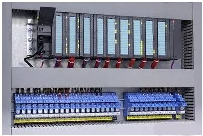
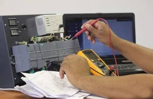
Since the PLC control system is composed of a variety of components, devices and other components, therefore, in order to do a good job in the overall system security, only the first step must be to control the system fault detection, in order to strictly check the various potential Risk factors. The PLC control system fault detection mainly has the following four steps: First, the basic operation flow of the system is detected. That is to say, firstly, the relatively simple basic functions in the system are checked one by one. For example, whether the input and output functions of the system are normal is normal. After the basic detection of the system is completed, it is determined whether the initial stage of the system is faulty; Detection. After completing the basic detection of the system, if no fault is found, it is necessary to detect all the faults that may occur in the entire control system to determine the security of the system: Third, fault isolation. When the faulty part of the system is detected, the fault is actively isolated; the fourth is fault evaluation and decision making. In order to identify the faults, it is necessary to conduct in-depth analysis and judgment, and take corresponding measures and evaluations. 1 visual inspection method First of all, the overall visual inspection of the PLC system can be carried out to timely check the risk factors in the system. For example, some parts that have entered the loss period should be replaced regularly; take appropriate measures for the factors that have been found to be safe for the system. Therefore, only after familiarizing and understanding the various modules of the entire system can you truly grasp the area where system failures may be distributed. 2 macroscopic diagnosis The macroscopic diagnosis method refers to the diagnosis of the fault caused by the diagnosis according to the existing work experience, that is, the cause and the area of ​​the fault are judged according to the surface phenomenon of the system failure, and the power supply is turned on and the line is checked in time. Whether it is correct, whether the field operation is standardized or not. 3 microscopic detection method The microscopic detection method is mainly for the software design failures that may occur in the system. Once this happens, the hardware design and software design of the system should be checked. For example, for CPU fault detection. CPU failure is mainly manifested in the corresponding LED light is not on or the CPU unit is shut down. When this happens, the following three reasons are mainly considered: First, the power supply cannot work due to noise interference; Second, the electrical components on the CPU internal bus have failed; Third, the CPU control program is lost. Therefore, for the CPU software failure, it is necessary to judge the specific cause of the failure according to the actual situation of each region. If the fault is caused by noise interference, then you need to restart the CPU to start the system. If there is a problem inside the program, then you need to reload or modify the system program. 4 dynamic detection method In the whole control system work, since the components of each part and the controller itself are running, these controllers and components may malfunction anytime and anywhere. Therefore, in order to detect the cause of the fault in time, there are It is necessary to conduct a comprehensive and dynamic test of the system. The dynamic detection of the system can be realized by design software, and the whole process of fault occurrence is detected in real time through software monitoring. The specific work is mainly done in the following three steps: First, input detection. This part mainly realizes the detection and conversion function of each switch quantity feedback signal outside the system; the second is the system state transition. This part mainly realizes the signal detection and historical status of each area in the system: The third is output detection. This part determines the state of each control signal mainly based on the current state of the system. The PLC control system can realize the full control of the system by sequentially performing these three steps in one monitoring cycle. There are two types of EPON systems: one is a system that uses 2 wavelengths; the other is a system that uses 3 wavelengths. Epon Wifi Onu,Epon 1Ge Wifi Onu,Epon 4Ge Wifi Onu,Wifi Onu, FTTX solution, HGU ONU Shenzhen GL-COM Technology CO.,LTD. , https://www.szglcom.com

For a two-wavelength system, its downlink wavelength is 1510 nm to transmit downlink voice, data and digital video services; the uplink wavelength is 1310nm to transmit uplink voice and video on-demand and download data request signals. The two-way transmission rate of this system is 1.25 Gb/s, even if the OBD split ratio is 32, it can transmit 20km.
For the three-wavelength system, in addition to the downlink wavelength of 1510 nm and the uplink wavelength of 1310 nm, a transmission window with a downlink wavelength of 1550 nm (1530 ~ 1565 nm) is added. The new window is used to transmit downlink CATV service or DWDM service. The CATV service can be either an analog video signal or an MPEG-2 digital video signal. When the splitting ratio of this system is 32, it can transmit 18 km.
EPON is located between the business network interface and the user network interface, connected to the business node through SNI, and connected to user equipment through UNI. EPON system is mainly composed of optical line terminal (OLT), optical distribution network (ODN) and optical network unit.
In the EPON system, the OLT is not only a switch or router, but also a multi-service providing platform, which provides optical fiber interfaces for passive optical fiber networks. According to the development trend of Ethernet to metropolitan area network and wide area network, OLT will provide 1 Gb/s and 10 Gb/s Ethernet interfaces. In addition to supporting traditional voice, ordinary telephone lines, and other types of T1/E1 interfaces, the OLT also supports SONET connections at ATM, FR, and OC3/12/48/192 rates. The OLT in the EPON can be configured with multiple optical line cards as required to connect with 16 to 64 ONUs. In EPON, the maximum distance from the OLT to the ONU can reach 20 km. If an optical fiber amplifier (active repeater) is used, the distance can be extended.