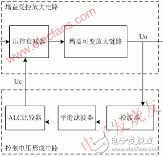
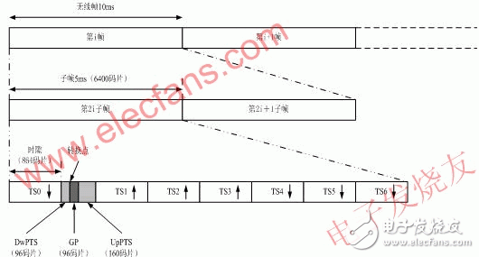
The ALC (AutomaTIc level control) discussed in this paper is an extremely important part of the repeater system. It refers to increasing the input signal level when the amplifier output signal level reaches the ALC setting. The ability to control the output signal level. For the repeater, the function realized by ALC technology is to control the output level on the one hand to ensure that the power amplifier device will not work in the over-power state, and on the other hand, the output power of the control repeater can be within the coverage allowable range. It satisfies the coverage distance requirement during network planning, and does not generate excessive output signals to cause interference to neighboring base stations. 2.1 ALC control principle To increase the input signal level when the output signal reaches the set value, and the output signal level remains basically the same, that is, the gain of the amplifier circuit is automatically adjusted with the signal strength, so that the output level of the system is maintained. Within a certain range, it is therefore called automatic level control. A general ALC circuit can be divided into a gain controlled amplification circuit and a control voltage forming circuit. The working principle is as follows: Figure 1 ALC circuit working principle diagram The gain controlled amplification circuit is located in the forward amplification path and its gain varies with the control voltage. The basic components of the control voltage forming circuit are detectors and low-pass smoothing filters, and sometimes include components such as gates and DC amplifiers. The output signal Uo of the amplifying circuit is detected and filtered by the filter to filter out the low frequency modulated component and noise, and then compared with the set maximum output power to generate a voltage Uc for controlling the gain controlled amplifier. As the input signal Ui increases, Uo and Uc also increase. As a negative feedback network, Uc increases the gain of the amplifying circuit, so that the amount of change of the output signal is significantly smaller than the amount of change of the input signal, achieving the purpose of automatic gain control. That is to say, the main working principle of the ALC circuit is to control the voltage controlled attenuator with the DC ramping voltage of the reaction signal amplitude variation trend to achieve the purpose of controlling the output level. 2.2 Characteristics of TD-SCDMA signals Figure 2 TD-SCDMA signal structure The structure of the TD-SCDMA signal is as shown in the figure above. Its frame structure divides a 10ms radio frame into two 5ms subframes, each of which has 7 regular slots and 3 special slots. The three special time slots are a downlink pilot time slot DwPTS, a primary guard time slot GP, and an uplink pilot time slot UpPTS. TS0 is always assigned to the downlink in 7 regular time slots, and TS1 is always assigned to the uplink. By flexibly configuring the number of uplink and downlink time slots, TD-SCDMA is suitable for both uplink and downlink symmetric and asymmetric service modes. The uplink time slot and the downlink time slot are separated by a transition point. In a TD-SCDMA system, each 5ms subframe has two transition points: the first transition point is the GP from the downlink to the uplink, the location is between DwPTS and UpPTS; the second transition point It is from the uplink to the downlink, and the position is between the last uplink time slot and the second downlink time slot in each subframe, and TS0 is the first downlink time slot. The first transition point is fixed with respect to the start time of each subframe; the second transition point varies with the number of slots allocated to the uplink and downlink. Since TD-SCDMA integrates multiple multiplexing techniques of time division, frequency division, code division and space division, that is, each regular time slot at each frequency point can simultaneously carry multiple users, and these users are different. The spreading code is used to distinguish, and even after the smart antenna technology is more mature, it can even be distinguished from the spreading code according to space. The system dynamically allocates channels to users according to a certain DCA algorithm. The distances of multiple users in a certain time slot from the base station will be different, the speed of movement will be different, and different channel fading characteristics. In fact, in one subframe, different time slots have different code channel occupation conditions, resulting in a difference in power of each time slot, and the power of the same regular time slot of multiple consecutive subframes is also different. 2.3 ALC control scheme analysis It can be found from the signal sub-frame format of TD-SCDMA that this is a peak-to-average burst signal, rather than a continuous signal, which brings certain difficulties to the automatic level control of ordinary amplifiers. At this time, the automatic level control cannot respond immediately, and the automatic level control starts to respond, causing the burst signal to be distorted, and does not really play the role of automatic level control. And since each user can only be assigned one time slot in one subframe, the conventional level control has such a problem that when the level control is performed, the attenuation of the entire link is performed, so when some When the time slot power is too large, the entire link will be attenuated, which inevitably reduces the power of other time slots without over power, which inevitably affects other time slot users. Therefore, we propose a scheme for slotted ALC. 2.3.1 Hardware slotted ALC According to the control principle of ALC and the characteristics of TD-SCDMA subframe, the direct solution is to increase the reaction speed by reducing the time constant of the RC filter in the ALC loop, so that the ALC circuit is in each The gain control is performed once in the burst time of the time slot, but at the same time, when the time constant of the RC is small, the peak-to-average ratio TD burst signal frequently controls the voltage-controlled attenuator action through the RC low-pass filter. , causing the link gain to fluctuate within the time slot, causing the EVM indicator to deteriorate. 4U Atx Power Supply,Atx 1800W Server Power Supply,Atx 1800W Power Supply,Active Pfc Power Supply For Computer Boluo Xurong Electronics Co., Ltd. , https://www.greenleaf-pc.com

Research on ALC Control Scheme in Repeater System
1 Introduction