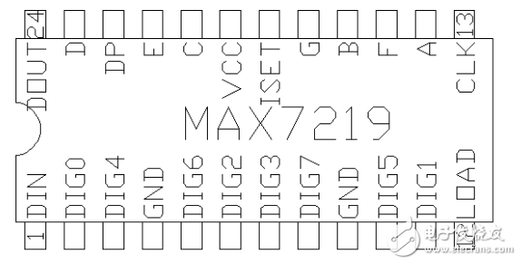
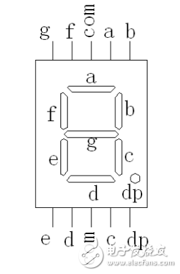
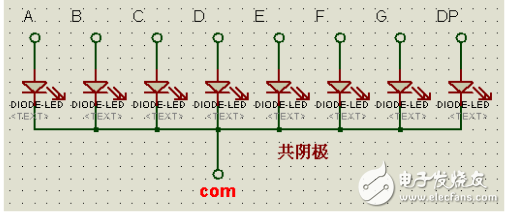
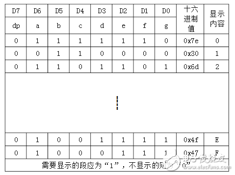
MAX7219 is a serial-in and parallel-out common cathode LED digital tube display driver, each of which can drive 8-bit LED digital tube display. It only needs 3 lines with the interface of the single-chip microcomputer, with BCD decoder and display test. Shift, latch, etc., the output current is up to 40mA, and only one brightness adjustment resistor is needed on the periphery. MAX7219 pin diagram DIN: serial data input, data is loaded into the internal 16-bit shift register on the rising edge of CLK CLK: serial clock input, up to 10MHz LOAD: Chip select terminal, low level receives data from DIN terminal, data is stored when high level DIG0~7: LED control terminal A~DP: LED terminal control terminal DOUT: serial data output for cascading of chips ISET: hardware brightness adjustment terminal, a resistor is connected between the pin and VCC, the brightness of the LED can be adjusted by the resistor, and the average current flowing through the segment of the LED is 100 times of the current flowing through the resistor. The resistance value ranges from 10 to 80K. A, decoding mode selection register address: 09H Assignment: FFH indicates the use of the BCD decoder inside the MAX7219 00H means not using the BCD decoder inside the MAX7219 B, brightness adjustment register address: 0AH Assignment: 00H~0FH can change the brightness of the LED driven by the MAX7219, which varies from 1/32 to 31/32. C, scan digit setting register address: 0BH Assignment: 00H All bits are not displayed 01H~07H corresponds to 1~8 digits and all the previous digits are displayed (the bit to be displayed should be "1") D, standby mode switch register address: 0CH Assignment: 00H LED is completely off 01H LED display normally E, display test register address: 0FH Assignment: 00H LED is in normal display state 01H LED test status, that is, LED is fully illuminated F, 8-bit LED display data register address: 01H~08H Assigning values ​​to these registers (that is, what needs to be displayed) will be displayed on the corresponding 1~8-digit LED digital tube. Due to noise in the power supply or nearby electromagnetic interference signals, the MAX7219 does not display or display after power-on; to eliminate this phenomenon, a 104pf ceramic capacitor should be connected between the VCC terminal of the MAX7219 and ground. Connect a 10K resistor to the ground. The most is also a high-frequency inductor between the power supply and the VCC end of the MAX7219. In terms of power supply, it is best to use a transformer to supply power instead of a switching power supply. The serial data added to the DIN pin must be shifted to 1 bit of data on every rising edge of the SCK pin signal when the LOAD pin is low, once every 2 bytes, and the high bit is at the previous low bit, then at The rising edge of the LOAD signal is stored in the MAX7219. The segment code table is displayed as follows:
It is used for continuous level measurement. The signal transmitted by its sensor is collected by the receiving system after being reflected by the target, and the distance of the target is determined by measuring the reflection running time. Then the level distance is converted into an output signal and output as a measured value.
The liquid level radar is applicable to the continuous non-contact liquid level measurement of liquid cargo tanks and overflow tanks of oil tankers and chemical carriers. It is also applicable to the liquid level monitoring of other oil tanks, towers, tank equipment and oil production platforms. Its measurement results are not affected by medium replacement, temperature change and gas or steam coverage.
Radar Level Gauge Sensor,Level Gauge Sensor,Level Sensor Durable,Durable Radar Level Gauge Sensor Taizhou Jiabo Instrument Technology Co., Ltd. , https://www.taizhoujiabo.com


MAX7219 driving common cathode LED schematic and program
1. Introduction to MAX7219