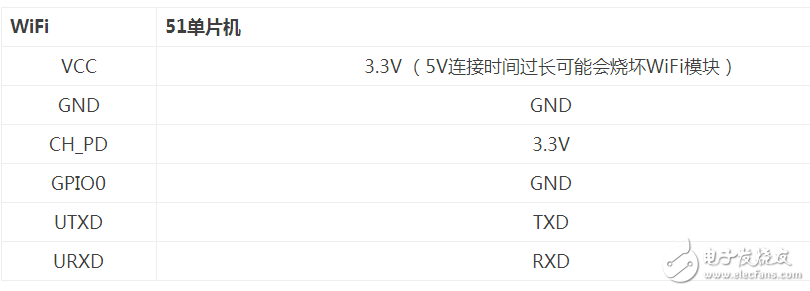
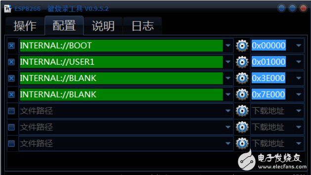
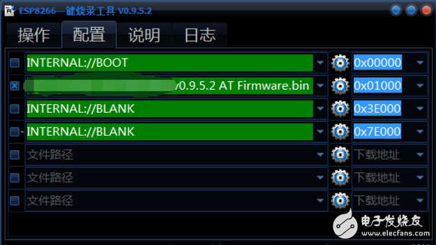
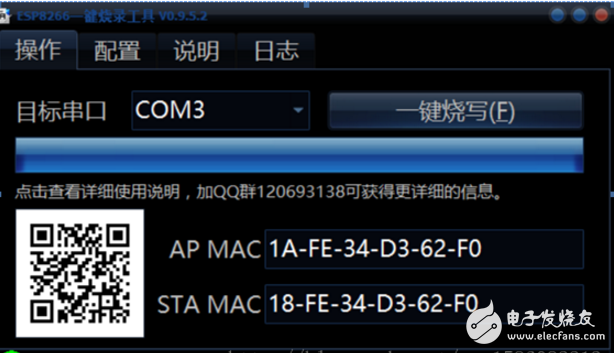
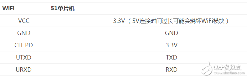
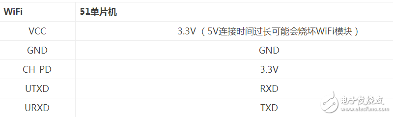
51 MCU is a general term for all MCUs compatible with Intel 8031 ​​instruction system. The first ancestor of this series of MCUs is Intel's 8004 MCU. Later, with the development of Flash rom technology, the 8004 MCU has made great progress and become one of the most widely used 8-bit MCUs. Its representative model is ATMEL's AT89 series. Widely used in industrial measurement and control systems. Many companies have launched 51 series compatible models, which will occupy a large number of markets for a long time to come. 51 single-chip microcomputer is a single-chip computer that is the basic introduction, or the most widely used one. It should be noted that the 51 series of single-chip microcomputers generally do not have self-programming capabilities. The same piece of program, the results of running on the hardware of each microcontroller manufacturer are the same, such as ATMEL 89C51 (has been discontinued), 89S51, PHILIPS, and WINBOND, etc., we often say that 89C51 has been discontinued refers to ATMEL company The AT89C51 MCU has enhanced many features, such as clocks, on the basis of the original. It is better to replace the original ROM (one-time write) by the memory of Flash (the program memory can be rewritten at least 1000 times). The performance of AT89C51 Compared with the 8051, it is already very advantageous. However, in terms of marketization, the 89C51 has been challenged by the PIC microcontroller camp. The most fatal flaw of the 89C51 is that it does not support the ISP (Online Update Program) function. It must add new features such as the ISP function to better extend the legend of the MCS-51. 89S51 is to replace 89C51 in this background, 89S51 has become a new darling in the practical application market, as the market share of the first Atmel company has discontinued AT89C51, will be replaced with AT89S51. The 89S51 has been improved in terms of technology. The 89S51 uses a new 0.35 process, which reduces costs and increases functionality and competitiveness. The 89SXX can be backward compatible with 51 series chips such as 89CXX. At the same time, Atmel no longer accepts orders from 89CXX. The 89C51 that everyone sees on the market is actually a huge inventory of Atmel's pre-production. If the market needs it, Atmel can of course resume production of the AT89C51. Pin connection Burn firmware Open the burning software, select the Configuration tab, click the pinion icon in the second column - Load Firmware Address Click the selection bar of other options, uncheck, select only the second option (firmware address) Return to the operation tab, select the correct COM port, click one button to burn The module is powered back on, the download starts, and the download is complete. Serial assistant test ESP8266 serial WiFi module Pin connection Note: At this time, the connection status WiFi module – “51 MCU –†serial port assistant (PC), because the WiFi module and the TXD and RXD of the MCU are in the positive connection state, the MCU and the WiFi module do not communicate, which is equivalent to the WiFi module directly connected to the serial port assistant. AT common instructions The ESP8266 serial WiFi module is divided into three working modes: StaTIon mode (similar to wireless terminal), AP mode (providing wireless access service), AP mode and StaTIon mode. When testing the WiFi module through the serial port assistant, test Send instruction: AT Response: OK Restart module Send command: AT+RST Response: OK Setting module Send command: AT+CWMODE = "mode" Description: It takes effect after restart (AT+RST) Mode: 1-StaTIon mode, 2-AP mode, 3-AP and StaTIon mode. Response: OK Configuring AP parameters send command: Instruction: AT+ CWSAP= "ssid", "pwd", "chl", "ecn" Description: The command is valid only after the AP mode is enabled. Ssid: string parameter, access point name "pwd": string parameter, password up to 64 bytes, ASCII "chl": channel number Ecn: Encryption mode, 0-OPEN, 1-WEP, 2-WPA_PSK, 3-WPA2_PSK, 4-WPA_WPA2_PSK Example: AT+CWSAP=â€TESTâ€,â€123456123456â€,1,3 Response: OK Turn on multi-connect mode Send command: AT+CIPMUX=“mode†Description: "mode": 0-single connection mode, 1-multiple connection mode Response: OK Create server Send command: AT+CIPSERVER=“modeâ€, “port†Note: The server can be enabled only when AT+ CIPMUX=1; the server mode needs to be restarted. Server startup is automatically established after the server is started. When a client accesses, it automatically takes up one connection in sequence. Mode: 0-off server mode, 1-on server mode Port: port number, default is 333 Response: OK Initialize the WiFi module through 51 MCU By testing the AT command through the serial port assistant, it can be found that some AT commands are not saved when they are powered off, so it is necessary to initialize the settings in the code. Pin connection Note: At this time, the connection status WiFi module – “51 MCU –†serial port assistant (PC), because the WiFi module and the TXD and RXD of the MCU are in the positive connection state, the MCU and the WiFi module can perform serial communication. Implementation code #include"reg52.h" //51 commonly used header files #define uchar unsigned char //The macro defines an unsigned char type #define uint unsigned int //The macro defines an unsigned int type //Send one byte Void sendByte(uchar b) { SBUF = b; While(!TI); TI=0; } / / Send string Void sendString(uchar *s) { While(*s != '\0') //The default ending string '\0' is used to determine the end of the string { sendByte(*s); s++; } } / / Initialize the ESP8266WiFi module Void initEsp() { Uint a; SCON = 0x50; //8-bit data, variable baud rate TMOD = 0x20; //Set timer 1 bit 16-bit auto reload mode TL1 = 0xfd; //Set the initial value of the timer, the baud rate is 9600 TH1 = 0xfd; ET1 = 0; // disable timer 1 interrupt TR1 = 1; //Start timer 1 EA = 1; For (a=0; a "50000; a++); / / delay a few seconds, let the module have time to start sendString("AT+CWMODE=2"); //Set to softAP and station coexistence mode / / WiFi hotspot can not be set by code, you can use the serial port assistant to set, the setting is not lost /* For (a=0; a "20000; a++); sendString("AT+CWSAP='TEST','12345678',1,3"); //Create a WiFi hotspot */ For (a=0; a "50000; a++); sendString("AT+CIPMUX=1"); //Start multiple connections For (a=0; a "20000; a++); sendString("AT+CIPSERVER=1,333");//Create server, port is 333 For (a=0; a "20000; a++); sendString("AT+CIPSTO=50"); //Server timeout setting RI=0; ES=1; //Initialization completed, serial port interrupted open } / / Main function Void main() { initEsp(); } Note: The baud rate in the code should match the baud rate of the serial port assistant, and some AT commands such as restarting the module, setting the WiFi hotspot and other instructions cannot be used. Get data transmitted by WiFi The ESP8266 WiFi module accepts +IPD,n, "string.length" as a TCP server before accepting information from the client. It should be noted when processing. Implementation code / / Get data, data format example: +IPD, 0, 14: "time": "11:11" Void getData() { Uint a; If(receiveFlag) { For(i=0; i“2; i++) { Hour[i]=Buffer[17+i]; } Hour[2]='\0'; For(i=0; i“2; i++) { Minute[i]=Buffer[20+i]; } Minute[2]='\0'; / / Send the obtained data to the serial port assistant to display For (a=0; a "10000; a++); / / need to delay, responsible for data corruption caused by packet loss sendString(Hour); For (a=0; a "10000; a++); sendString(Minute); receiveFlag=0; Count=0; For(i=0; i“22; i++) { Buffer[i]=0; } } } / / Main function Void main() { initEsp (); / / initialize the WiFi module receiveFlag = 0; //receiveFlag determines the flag to execute getData() Count = 0; //index of the count buffer RXDdata[count] While(1) { getData(); } } / / Use interrupt to receive information, and discard invalid information Void uart() interrupt 4 { If(RI == 1) { ES = 0; //turn off serial interrupt RI = 0; //Clear the serial port receive flag Temp = SBUF; //Get data from the serial buffer If (count "20) / / meet the length of the information to be received, save the data in the buffer { Buffer[count]=temp; Count++; If(Buffer[0]=='+') //Determine whether it is invalid data, because the WiFi module will automatically add the string starting with "+PID.." { receiveFlag = 1; } Else { receiveFlag = 0; Count = 0; } } ES = 1; } } RandM Tornado 9000 is a new Disposable Vape device It contains 18ml 5% nic salt e-juice and vape up to 9000 puffs. It's recharge, The rechargeable port at the bottom of the device guaranteeing you finish the last drop of the ejuice in the tank all the time. The price of the randm tornado 9000 is very good price, if you want to buy randm tornado 9000 near me, please contact us. Tornado 9000 Puffs, RandM 9000, Randm Tornado 9000, 9000 puff disposable, 9000 Puffs vape Shenzhen Kate Technology Co., Ltd. , https://www.katevape.com