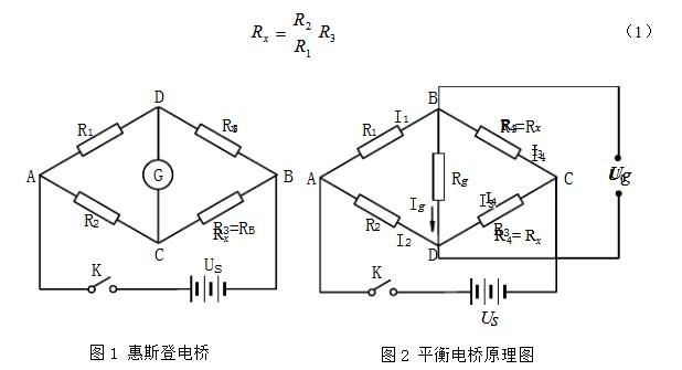
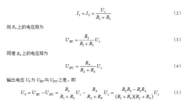
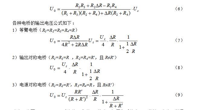
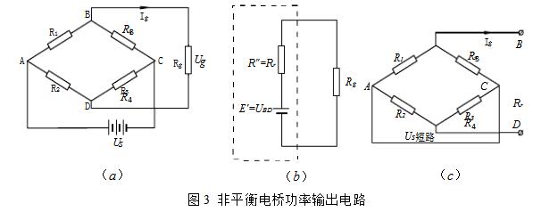
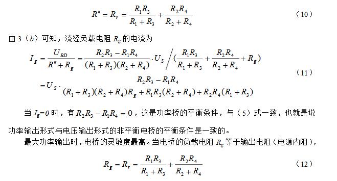
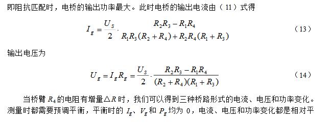
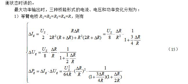
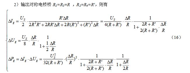
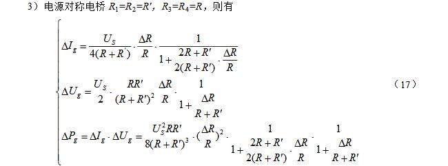
Bridges can be divided into balanced bridges and unbalanced bridges by measuring methods. Although they all accurately measure resistance, balanced bridges can only be used to measure relatively stable resistance values, whereas non-equilibrium bridges can be used to measure continuously varying resistance values. The principle of the Wheatstone bridge (balanced bridge) is shown in Fig. 1. When R3 is adjusted so that no current flows through the galvanometer G, C and D are equalized at two points and the bridge is balanced. Unbalanced bridges are also called unbalanced bridges or differential bridges. Figure 2 is a schematic diagram of an unbalanced bridge. Between B and D is a load resistance Rg. When measuring resistance with an unbalanced bridge, R1, R2, and R3 are held constant, and U0 changes when Rx (ie, R4) changes. Then according to the function relationship between U0 and Rx, Rx is measured by detecting the change of U0. Since continuously variable U0 can be detected, continuously changing Rx can be detected. (1) Bridge form of unbalanced bridge 1) Equal-arm bridge The four bridges of the bridge have the same resistance, that is, R1 = R2 = R3 = R4. 2) Output symmetrical bridge, also known as horizontal bridge At this time, the bridge arm resistance of the bridge is symmetrical to the output end, that is, R1=R3=R and R2=R4=R'. And R≠R'. 3) Power symmetrical bridge, also known as vertical bridge At this time, the resistance of the bridge arm is viewed from the power supply end of the bridge, that is, R1=R2=R′, R3=R4=R, and R≠R′. 4) Proportional bridge At this time, the resistance of the bridge arm has a certain proportional relationship, that is, R1 = KR2, R3 = K R4 or R1 = K R3, and R2 = K R4. K is a proportional coefficient. In fact this is a general form of unbalanced bridge. (2) Unbalanced bridge (voltage output form) when Rg is relatively large When the load resistance Rg → ∞, that is, the bridge output is in an open circuit state, Ig = 0, only the output voltage, with U0 said. The voltage drop of the ABC half-bridge is Us (ie, the supply voltage). According to the principle of voltage division, the current through the R1 and R3 arms is When the condition R2R3 = R1R4 is satisfied, the bridge output U0 = 0, ie, the bridge is in equilibrium. In order to measure the accuracy, at the beginning of the measurement, the bridge must be adjusted to balance, called pre-balanced. Pre-balancing makes the output only relevant to the resistance change of an arm. If R1, R2, and R3 are fixed, R4 is the resistance to be measured. When R4 changes to R4 + ΔR due to changes in external conditions (such as temperature t), the output voltage generated due to the bridge no longer being balanced is Note that R and R′ in the above formulas (7)-(9) are pre-balanced resistors. In addition, when the resistance increase ΔR is small, that is, when satisfying ΔR "R, the denominator of the above three equations (7) to (9) can be omitted, and the formula can be simplified, which is omitted here. In general, the output voltage of the isobaric bridge and the output symmetrical bridge is higher than that of the symmetrical bridge of the power supply, so the sensitivity is also high, but the measuring range of the symmetrical bridge of the power supply is large, and the measurement range can be expanded by selecting R and R′. The greater the difference between R and R', the larger the measurement range. When using the unbalanced bridge to measure the resistance, the measured resistance Rx needs to be connected to the unbalanced bridge as the bridge arm R4 and pre-balanced. The bridge output voltage is 0 at this moment. Change the external conditions (such as temperature t), then the measured resistance changes, then the bridge output voltage U0 ≠0, began to make the corresponding changes. After this voltage U0 is measured, ΔR can be calculated according to equations (7)-(9), and Rx = R4 + ΔR can be obtained. (3) Unbalanced bridge (power output form) when Rg is comparable to the arm resistance When the load resistance Rg is comparable to the arm resistance, the bridge not only has the output voltage Ug but also the output current Ig. With output power, this kind of bridge is also called a power bridge. The power bridge can be represented as Figure 3(a). Applying the active port network theorem, the power bridge can be simplified to the circuit shown in Figure 3(b). UBD is the open circuit voltage between BD, represented by formula (5), R′′ is the resistance in the equivalent branch of the active end network, and its value is equal to the in-end resistance Rr of the network. Refer to Figure 3(c). The 2.7kΩ MF51 type semiconductor thermistor is made of a transition metal oxide (mainly made of Mn, Co, Ni, and Fe, etc. oxides) and a semiconductor metal oxide formed under certain sintering conditions as a basic material. Semiconductor characteristics. For general semiconductor materials, the change in resistivity with temperature mainly depends on the carrier concentration, and the mobility variation with temperature is relatively negligible. However, the above transition metal oxides are different, and they are basically completely ionized in the room temperature range, ie, the carrier concentration is basically independent of the temperature, and the relationship between the mobility and the temperature is mainly considered at this time. As the temperature increases, the mobility increases and the resistivity decreases, so this type of metal oxide semiconductor is a thermistor element having a negative temperature coefficient. The resistance-temperature characteristics are shown in Table 1. According to theoretical analysis, the mathematical expression of the resistance-temperature characteristic of a semiconductor thermistor can often be expressed as Where R25 and Rt are the thermistor resistances at 25°C and t°C respectively, T = 273 + t; Bn is the material constant, and the value varies depending on the processing method used to make it. For the specified thermistor, you can Obtained from the experimentally measured resistance-temperature curve. We can also write (19) as a relatively simple expression Siren Horn,Alarm Horn,Police Horn Chinasky Electronics Co., Ltd. , https://www.chinacctvproducts.com