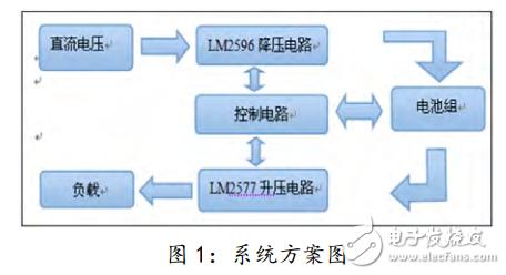
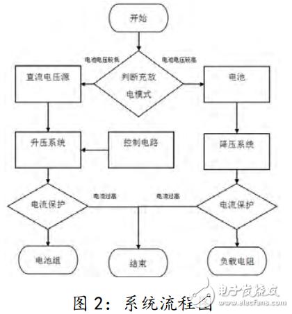
1.1, program design This program uses the single-chip microcomputer as the main design measurement and control circuit. By monitoring the output current of the DC-DC converter, the input and output current setting signals are input through the keyboard, and the PWM signal is outputted by the single-chip microcomputer to form a comparison voltage with the LM358 comparator, and the current feedback closed-loop circuit controls the LM2596 chip to control the buck circuit. Turn on and off to ensure DC-DC conversion. The boosting section is directly controlled by the LM2577 circuit and its structure is shown in Figure 1. 1.2, control system design The LM2577 and LM2596 are used to design the boost circuit and the buck circuit. The buck circuit works well with the measurement and control circuit, and the cost is also low. The circuit diagram is also easy to be welded and debugged. Using the MCU to form the measurement and control circuit, we can more conveniently use the keyboard to control the voltage and current output by the converter. The feedback circuit of the main circuit detects the current and samples it to adjust the PWM to achieve the functions of control output and overcurrent protection. The measurement and control circuit of the single-chip microcomputer is simpler, the components used are less, and the control is more convenient, so the scheme is adopted. 1.2.1, boost system In the case of DC-DC battery pack discharge, the boost boost circuit is used as the core circuit. The essence lies in the LM2577 chip as a switch. When the chip is working, the 4 and 5 pins are turned on to charge the L1 inductor, and the 4 and 5 pins are turned off. The inductor L1 slowly charges the capacitor. The output is boosted by the turn-on and turn-off of the 4 and 5 pins. At the same time, the 2 pin is the output feedback terminal, so that the output voltage is stable and does not change, that is, it acts as a voltage regulator. 1.2.2, step-down system When the DC-DC converter is used to charge the battery pack, the buck step-down circuit is used as the core circuit. The essence lies in the LM2596 chip as a circuit switch. When the circuit is working, the 2 pin is turned on to charge the L2 inductor capacitor C. When the 2 pin is turned off, the inductor and the capacitor are slowly discharged to maintain the voltage. The LM2596 chip has a 4-pin regulated feedback input and is fed back to the 4-pin stable output voltage via resistors R4 and R5. The charging current is detected by the sampling resistor and is collected by the LM358 comparator and compared with the current PWM signal generated by the Freescale microcontroller to control the charging current. 1.3, system flow chart <br> as shown in Figure 1, Figure 2. 3.1, test plan 3.1.1, hardware debugging (1) Test the input 20V voltage in the boost module (with load), adjust the potentiometer to make its output accurate to 30V. (2) Test input 30V DC voltage in the buck module, and use the adjustable analog voltage input current PWM to test whether the charging current is adjustable. (3) Under the output analog short-circuit state, see if there is a function of the protection circuit, and whether the system can resume the charging function after the short-circuit condition is removed. In the fourth step, the output voltage and current of the battery pack charging and discharging states are respectively tested. 3.1.2, software debugging (1) Write the AD function program through Freescale microcontroller, and test the AD voltage value output data with a 5-digit half-voltmeter. (2) Test the keyboard function to ensure that the output data is accurate and the keyboard function is reliable when the button is pressed. 3.2, test results and analysis Efficiency when charging: 96.6% for the first time, 96.1% for the second time, and 96.8% for the third time. Efficiency at discharge: 91.1% for the first time, 91.8% for the second time, and 92.0% for the third time. Basic requirements: Turn on S1, S2, disconnect S3, and set the device to charging mode. (1) Under the condition of U2=30V, the constant current charging of the battery is realized. The charging current I1 is step-adjustable in the range of 1-2A, the step value is not more than 0.1A, and the current control accuracy is not less than 5%. (2) Set I1=2A, adjust the output voltage of the DC stabilized power supply, and make the change rate of the charging current I1 not more than 1% when U2 changes within the range of 24-36V. (3) Set I1=2A, and the efficiency of the converter is 90% under the condition of U2=30V. (4) The charging current I1 is measured and displayed, and the measurement accuracy is not less than 2% in the range of I1=1-2A. Play part: 1) Disconnect S1, turn on S2, set the device to the floating point mode, keep U2=30±0.5V, and the converter efficiency at this time. 2) Turn on S1, S2, disconnect S3, adjust the output voltage of DC stabilized power supply, and make the bidirectional DC-DC circuit automatically change the working mode and keep U2=30±0.5V when Us changes within the range of 32-38V. 3) The total weight of the three-way DC-DC converter, the measurement and control circuit and the auxiliary power supply is not more than 500g. Led Membrane Switch,Membrane Switch With Led ,Led Light Membrane Switch ,Membrane Switch With Lcd Display CIXI MEMBRANE SWITCH FACTORY , https://www.cnjunma.com 1, system design
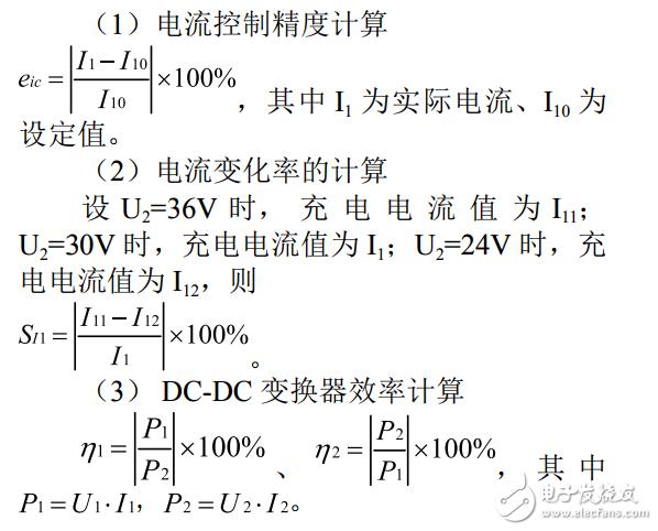
2. Theoretical analysis and calculation formula
3. Test plan and test results
4, the results of the analysis
Power converter design based on UC3842
0 times
Window._bd_share_config = { "common": { "bdSnsKey": {}, "bdText": "", "bdMini": "2", "bdMiniList": false, "bdPic": "", "bdStyle": " 0", "bdSize": "24" }, "share": {}, "image": { "viewList": ["qzone", "tsina", "tqq", "renren", "weixin"], "viewText": "Share to:", "viewSize": "16" }, "selectShare": { "bdContainerClass": null, "bdSelectMiniList": ["qzone", "tsina", "tqq", "renren" , "weixin"] } }; with (document) 0[(getElementsByTagName('head')[0] || body).appendChild(createElement('script')).src = 'http://bdimg.share. Baidu.com/static/api/js/share.js?v=89860593.js?cdnversion=' + ~(-new Date() / 36e5)];