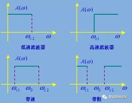
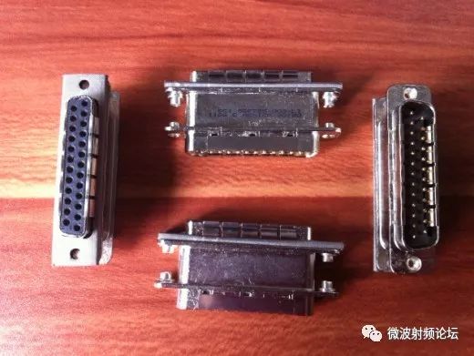
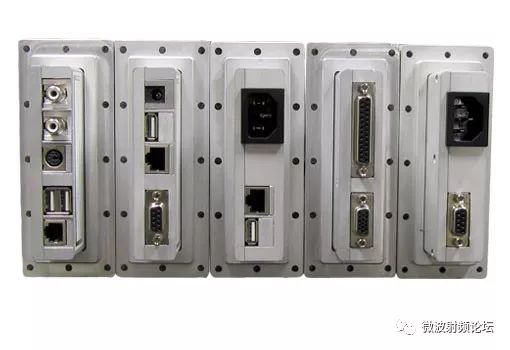
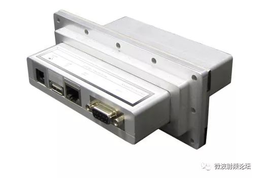
A filter is a network of resistors, inductors, and capacitors that concentrate parameters, or resistors, inductors, and capacitors that distribute parameters. This network allows some frequencies to pass while suppressing other frequency components. The interference filter has a low-pass filter, a high-pass filter, a band-pass filter, a band-stop filter, and the like according to the relative relationship between the frequency of the interference signal to be filtered and the operating frequency. The low-pass filter is the most commonly used one, and is mainly used when the interference signal frequency is higher than the operating signal frequency. For example, in digital devices, pulse signals have abundant high-order harmonics. These high-order harmonics are not necessary for circuit operation, but they are strong sources of interference. Therefore, in the digital circuit, a common low-pass filter filters out unnecessary higher harmonics in the pulse signal, and only retains the lowest frequency that can maintain the normal operation of the circuit. The power line filter is also a low-pass filter that allows only 50 Hz of current to pass, which greatly attenuates other high-frequency interference signals. ◠A commonly used low-pass filter is a combination of an inductor and a capacitor. The capacitor is connected in parallel between the signal line to be filtered and the signal ground (filtering differential mode interference current) or between the signal line and the chassis ground or ground. (Filter out common mode interference current) The inductor is connected in series on the signal line to be filtered. According to the circuit structure, there are single capacitor type (C type), single inductor type, L type and reverse type, T type, π type. ◠High-pass filter is used when the interference frequency is lower than the signal frequency, such as the interference caused by power supply harmonics on some sensitive signal lines close to the power line. ◠Bandpass filter is used when the signal frequency only occupies a narrow bandwidth. For example, a bandpass filter is installed on the antenna port of the communication receiver, and only the communication signal is allowed to pass. ◠The band-stop filter is used for interference frequency band narrowness, and when the signal frequency is wide, such as a band-stop filter with a band-stop frequency equal to the station's transmission frequency at the cable port close to the high-power station. There are two main differences between the different types of filter circuits: 1. The more filter components in the circuit, the greater the attenuation of the filter stopband and the shorter the transition between the filter passband and the stopband. 2. Filter circuits of different structures are suitable for different source impedances and load impedances, and their relationship should follow the principle of impedance mismatch. However, it should be noted that the impedance of the actual circuit is difficult to estimate, especially at high frequencies (electromagnetic interference problems often occur at high frequencies). Due to the influence of circuit parasitic parameters, the impedance of the circuit varies greatly, and the impedance of the circuit is often It is also related to the operating state of the circuit, plus the circuit impedance is different at different frequencies. Therefore, in practice, which filter is effective depends mainly on the results of the test. Filter interface LED Lighting Zinc Alloy Die Casting Led Lighting Zinc Alloy Die Casting,Aluminum Alloys Die Casting,Aluminum Zinc Alloy Die Casting,Motor Housing Parts Casting Dongguan Metalwork Technology Co., LTD. , https://www.dgdiecastpro.com