EIGRP uses metrics to determine the best path to the destination. For each subnet, the EIGRP topology table contains one or more possible routes. Each possible route contains various metrics: bandwidth, latency, and so on. The EIGRP router calculates an integer metric based on the metric to select the best route to the destination. When the router is routing, the path with the lowest metric, FD, is calculated to determine the best route. When the route fails, FS is used to select an alternate route. How to create a preferred route by affecting Enhanced Interior Gateway Routing Protocol (EIGRP) metrics. Based on the topology shown in the network diagram, this document describes several methods for affecting IP traffic from the client to the server, where the preferred path is R1 "R2" R3. The goal is to make path R1 "R2" R4 an alternate path to be used only if there is a failure on R3. Claim This document requires a basic understanding of IP routing and EIGRP routing. For more information on IP routing and EIGRP, see the following documents: Routing basics Enhanced Interior Gateway Routing Protocol Components used The information in this document is based on the following software and hardware versions. EIGRP is supported in Cisco IOS® Software Release 9.21 and later. The information in this document is based on Cisco IOS Software Release 12.3(3). EIGRP can be configured on all routers, such as the Cisco 2500 Series and Cisco 2600 Series, and all Layer 3 switches. The information in this document is based on devices in a specific lab environment. All devices used in this document are initially configured in their original (default) configuration. If you are using a real network, make sure you understand the potential impact of all commands. rule For more information on file rules, refer to. Background Information There are several ways to set a preferred route by affecting EIGRP metrics. This document describes these methods and details their strengths and weaknesses. This document also discusses the impact of modifying bandwidth, but modifying bandwidth in this case is not a viable means of changing paths. Clicking on the network map can be displayed in a separate browser window for later reference in this document. The two commands used to verify EIGRP behavior in this document are show ip eigrp topology and show ip eigrp topology network-ip subnet-mask. If you have a show ip eigrp topology command or a show ip eigrp topology network-ip subnet-mask command from your Cisco device, you can use the Cisco CLI Analyzer Background - EIGRP Metrics Basics The EIGRP update contains five metrics: minimum bandwidth, latency, load, reliability, and maximum transmission unit (MTU). By default, only the lowest bandwidth and latency of these five metrics are used to calculate the best path. Unlike most metrics, the minimum bandwidth is set to the lowest bandwidth of the entire path and does not reflect the number of hops or low bandwidth links in the path. The delay is a cumulative value that increases as the delay value of each segment in the path increases. For more information on EIGRP metrics, see the Enhanced Interior Gateway Routing Protocol white paper. Possible configuration These configurations can be used to set up preferred routes. Default load sharing configuration R1 R1# show run Current configuration: 640 bytes ! Version 12.3 ! Hostname R1 ! Interface Serial0 No ip address Encapsulation frame-relay ! --- Enables Frame Relay encapsulation. ! Interface Serial0.201 point-to-point ! --- Enables a point-to-point link on the sub-interface. Ip address 10.1.1.1 255.255.255.0 Frame-relay interface-dlci 201 ! --- Assigns a data-link connection identifier (DLCI) ! --- to a Frame Relay sub-interface. ! Router eigrp 1 Network 10.0.0.0 ! End Note: The Frame Relay switch is hidden in the network map. R1# show ip route Codes: C - connected, S - static, I - IGRP, R - RIP, M - mobile, B - BGP D - EIGRP, EX - EIGRP external, O - OSPF, IA - OSPF inter area N1 - OSPF NSSA external type 1, N2 - OSPF NSSA external type 2 E1 - OSPF external type 1, E2 - OSPF external type 2, E - EGP i - IS-IS, L1 - ISIS level-1, L2 - ISIS level-2, * - candidate default U - per-user static route, o - ODR Gateway of last resort is not set 10.0.0.0/24 is subnetted, 3 subnets D 10.1.3.0 [90/2221056] via 10.1.1.2, 00:07:08, Serial0.201 D 10.1.2.0 [90/2195456] via 10.1.1.2, 00:07:08, Serial0.201 C 10.1.1.0 is directly connected, Serial0.201 R1# show ip eigrp topology 10.1.3.0 255.255.255.0 IP-EIGRP (AS 1): topology entry for 10.1.3.0/24 State is Passive, Query origin flag is 1, 1 Successor(s), FD is 2221056 Routing Descriptor Blocks: 10.1.1.2 (Serial0.201), from 10.1.1.2, Send flag is 0x0 Composite metric is (2221056/307200), Route is Internal Vector metric: Minimum bandwidth is 1544 Kbit Total delay is 22000 microseconds Reliability is 255/255 Load is 1/255 Minimum MTU is 1500 Hop count is 2 R2 R2# show run Current configuration: 618 bytes ! Version 12.3 ! Hostname R2 ! Interface Ethernet0 Ip address 10.1.2.2 255.255.255.0 No ip directed-broadcast ! ! Interface Serial0 No ip address Encapsulation frame-relay ! Interface Serial0.101 point-to-point Ip address 10.1.1.2 255.255.255.0 Frame-relay interface-dlci 101 ! Router eigrp 1 Network 10.0.0.0 ! End R2# show ip route Codes: C - connected, S - static, I - IGRP, R - RIP, M - mobile, B - BGP D - EIGRP, EX - EIGRP external, O - OSPF, IA - OSPF inter area N1 - OSPF NSSA external type 1, N2 - OSPF NSSA external type 2 E1 - OSPF external type 1, E2 - OSPF external type 2, E - EGP i - ISIS, L1 - ISIS level-1, L2 - ISIS level-2, * - candidate default U - per-user static route, o - ODR Gateway of last resort is not set 10.0.0.0/24 is subnetted, 3 subnets D 10.1.3.0 [90/307200] via 10.1.2.4, 00:03:47, Ethernet0 [90/307200] via 10.1.2.3, 00:03:48, Ethernet0 C 10.1.2.0 is directly connected, Ethernet0 C 10.1.1.0 is directly connected, Serial0.101 Note: R2 has two equivalent paths to 10.1.3.0/24, passing through R3 (10.1.2.3) and R4 (10.1.2.4). R2# show ip eigrp topology 10.1.3.0 255.255.255.0 IP-EIGRP (AS 1): topology entry for 10.1.3.0/24 State is Passive, Query origin flag is 1, 2 Successor(s), FD is 307200 Routing Descriptor Blocks: 10.1.2.3 (Ethernet0), from 10.1.2.3, Send flag is 0x0 Composite metric is (307200/281600), Route is Internal Vector metric: Minimum bandwidth is 10000 Kbit Total delay is 2000 microseconds Reliability is 255/255 Load is 1/255 Minimum MTU is 1500 Hop count is 1 10.1.2.4 (Ethernet0), from 10.1.2.4, Send flag is 0x0 Composite metric is (307200/281600), Route is Internal Vector metric: Minimum bandwidth is 10000 Kbit Total delay is 2000 microseconds Reliability is 255/255 Load is 1/255 Minimum MTU is 1500 Hop count is 1 Note: The composite metric (distance/report distance) for both paths is the same. The feasible distance (FD) to R1 is advertised and then becomes the reporting distance for R1. R3 R3# show run Current configuration: 556 bytes ! Version 12.3 ! Hostname R3 ! Interface Ethernet0/0 Ip address 10.1.2.3 255.255.255.0 No ip directed-broadcast ! Interface Ethernet0/1 Ip address 10.1.3.3 255.255.255.0 No ip directed-broadcast ! Router eigrp 1 Network 10.0.0.0 ! End R3# show ip route Codes: C - connected, S - static, I - IGRP, R - RIP, M - mobile, B - BGP D - EIGRP, EX - EIGRP external, O - OSPF, IA - OSPF inter area N1 - OSPF NSSA external type 1, N2 - OSPF NSSA external type 2 E1 - OSPF external type 1, E2 - OSPF external type 2, E - EGP i - ISIS, L1 - ISIS level-1, L2 - ISIS level-2, ia - ISIS inter area * - candidate default, U - per-user static route, o - ODR P - periodic downloaded static route Gateway of last resort is not set 10.0.0.0/24 is subnetted, 3 subnets C 10.1.3.0 is directly connected, Ethernet0/1 C 10.1.2.0 is directly connected, Ethernet0/0 D 10.1.1.0 [90/20537600] via 10.1.2.2, 00:16:14, Ethernet0/0 R3# show ip eigrp topology 10.1.3.0 255.255.255.0 IP-EIGRP (AS 1): topology entry for 10.1.3.0/24 State is Passive, Query origin flag is 1, 1 Successor(s), FD is 281600 Routing Descriptor Blocks: 0.0.0.0 (Ethernet0/1), from Connected, Send flag is 0x0 Composite metric is (281600/0), Route is Internal Vector metric: Minimum bandwidth is 10000 Kbit Total delay is 1000 microseconds Reliability is 255/255 Load is 1/255 Minimum MTU is 1500 Hop count is 0 10.1.2.4 (Ethernet0/0), from 10.1.2.4, Send flag is 0x0 Composite metric is (307200/281600), Route is Internal Vector metric: Minimum bandwidth is 10000 Kbit Total delay is 2000 microseconds Reliability is 255/255 Load is 1/255 Minimum MTU is 1500 Hop count is 1 R3# show interface ethernet0/1 Ethernet0/1 is up, line protocol is up Hardware is AmdP2, address is 0050.7329.52e1 (bia 0050.7329.52e1) Internet address is 10.1.3.3/24 MTU 1500 bytes, BW 10000 Kbit, DLY 1000 usec, Reliability 255/255, txload 1/255, rxload 1/255 Encapsulation ARPA, loopback not set Keepalive set (10 sec) ARP type: ARPA, ARP Timeout 04:00:00 Last input 00:00:02, output 00:00:01, output hang never Last clearing of “show interface†counters never Input queue: 0/75/0/0 (size/max/drops/flushes); Total output drops: 0 Queueing strategy: fifo Output queue: 0/40 (size/max) 5 minute input rate 0 bits/sec, 0 packets/sec 5 minute output rate 0 bits/sec, 0 packets/sec 291 packets input, 28402 bytes, 0 no buffer Received 283 broadcasts, 0 runts, 0 giants, 0 throttles 0 input errors, 0 CRC, 0 frame, 0 overrun, 0 ignored 0 input packets with dribble condition detected 500 packets output, 50876 bytes, 0 underruns 0 output errors, 0 collisions, 2 interface resets 0 babbles, 0 late collision, 0 deferred 0 lost carrier, 0 no carrier 0 output buffer failures, 0 output buffers swapped out R4 R4# show run Current configuration: 549 bytes ! Version 12.3 ! Hostname R4 ! Interface Ethernet0/0 Ip address 10.1.2.4 255.255.255.0 No ip directed-broadcast ! Interface Ethernet0/1 Ip address 10.1.3.4 255.255.255.0 No ip directed-broadcast ! Router eigrp 1 Network 10.0.0.0 ! End R4# show ip route Codes: C - connected, S - static, I - IGRP, R - RIP, M - mobile, B - BGP D - EIGRP, EX - EIGRP external, O - OSPF, IA - OSPF inter area N1 - OSPF NSSA external type 1, N2 - OSPF NSSA external type 2 E1 - OSPF external type 1, E2 - OSPF external type 2, E - EGP i - ISIS, L1 - ISIS level-1, L2 - ISIS level-2, IA - ISIS inter area * - candidate default, U - per-user static route, o - ODR P - periodic downloaded static route Gateway of last resort is not set 10.0.0.0/24 is subnetted, 3 subnets C 10.1.3.0 is directly connected, Ethernet0/1 C 10.1.2.0 is directly connected, Ethernet0/0 D 10.1.1.0 [90/20537600] via 10.1.2.2, 00:17:08, Ethernet0/0 R4# show ip eigrp topology 10.1.3.0 255.255.255.0 IP-EIGRP (AS 1): topology entry for 10.1.3.0/24 State is Passive, Query origin flag is 1, 1 Successor(s), FD is 281600 Routing Descriptor Blocks: 0.0.0.0 (Ethernet0/1), from Connected, Send flag is 0x0 Composite metric is (281600/0), Route is Internal Vector metric: Minimum bandwidth is 10000 Kbit Total delay is 1000 microseconds Reliability is 255/255 Load is 1/255 Minimum MTU is 1500 Hop count is 0 10.1.2.3 (Ethernet0/0), from 10.1.2.3, Send flag is 0x0 Composite metric is (307200/281600), Route is Internal Vector metric: Minimum bandwidth is 10000 Kbit Total delay is 2000 microseconds Reliability is 255/255 Load is 1/255 Minimum MTU is 1500 Hop count is 1 Change the interface delay parameter of R4 Since the changes made to the delay metric are propagated to all downstream routers, changing the interface delay parameter is the preferred method of affecting path selection for the following two cases: The Ethernet segment 10.1.3.0/24 contains only servers and there are no other subnets after the 10.1.3.0/24 subnet. (This configuration is ideal for server farms.) You want to affect path selection for all routes learned through EIGRP neighbors on the 10.1.3.0/24 segment. Check for delays on the interface before making any changes. Its current settings are the same as for R3, as shown here. R4# show interface ethernet0/1 Ethernet0/1 is up, line protocol is up Hardware is AmdP2, address is 0050.7329.5321 (bia 0050.7329.5321) Internet address is 10.1.3.4/24 MTU 1500 bytes, BW 10000 Kbit, DLY 1000 usec, Reliability 255/255, txload 1/255, rxload 1/255 Encapsulation ARPA, loopback not set Keepalive set (10 sec) ARP type: ARPA, ARP Timeout 04:00:00 Last input 00:00:02, output 00:00:02, output hang never Last clearing of “show interface†counters never Input queue: 0/75/0/0 (size/max/drops/flushes); Total output drops: 0 Queueing strategy: fifo Output queue: 0/40 (size/max) 5 minute input rate 0 bits/sec, 0 packets/sec 5 minute output rate 0 bits/sec, 0 packets/sec 284 packets input, 27914 bytes, 0 no buffer Received 276 broadcasts, 0 runts, 0 giants, 0 throttles 0 input errors, 0 CRC, 0 frame, 0 overrun, 0 ignored 0 input packets with dribble condition detected 482 packets output, 49151 bytes, 0 underruns 0 output errors, 0 collisions, 2 interface resets 0 babbles, 0 late collision, 0 deferred 0 lost carrier, 0 no carrier 0 output buffer failures, 0 output buffers swapped out Change the delay value on the 10.1.3.0/24 network segment. Be cautious when choosing a new delay. You certainly don't want the increase in latency to cause R2 to no longer treat the route as a viable successor route. R4# configure terminal Enter configuration commands, one per line. End with CNTL/Z. R4(config)# interface ethernet0/1 R4(config-if)# delay 120 ! --- Delay is entered in tens of microseconds. R4(config-if)# end R4# Verify that the delay for this interface has been changed to 1200 microseconds. R4# show interface ethernet0/1 Hardware is AmdP2, address is 0050.7329.5321 (bia 0050.7329.5321) Internet address is 10.1.3.4/24 MTU 1500 bytes, BW 10000 Kbit, DLY 1200 usec, Reliability 255/255, txload 1/255, rxload 1/255 Encapsulation ARPA, loopback not set Keepalive set (10 sec) ARP type: ARPA, ARP Timeout 04:00:00 Last input 00:00:03, output 00:00:00, output hang never Last clearing of “show interface†counters never Input queue: 0/75/0/0 (size/max/drops/flushes); Total output drops: 0 Queueing strategy: fifo Output queue: 0/40 (size/max) 5 minute input rate 0 bits/sec, 0 packets/sec 5 minute output rate 0 bits/sec, 0 packets/sec 345 packets input, 33508 bytes, 0 no buffer Received 333 broadcasts, 0 runts, 0 giants, 0 throttles 0 input errors, 0 CRC, 0 frame, 0 overrun, 0 ignored 0 input packets with dribble condition detected 575 packets output, 57863 bytes, 0 underruns 0 output errors, 0 collisions, 2 interface resets 0 babbles, 0 late collision, 0 deferred 0 lost carrier, 0 no carrier 0 output buffer failures, 0 output buffers swapped out Confirm that R2 has only one "best" route to reach 10.1.3.0, that is, through R3. R2# show ip route Codes: C - connected, S - static, I - IGRP, R - RIP, M - mobile, B - BGP D - EIGRP, EX - EIGRP external, O - OSPF, IA - OSPF inter area N1 - OSPF NSSA external type 1, N2 - OSPF NSSA external type 2 E1 - OSPF external type 1, E2 - OSPF external type 2, E - EGP i - ISIS, L1 - ISIS level-1, L2 - ISIS level-2, * - candidate default U - per-user static route, o - ODR Gateway of last resort is not set 10.0.0.0/24 is subnetted, 3 subnets D 10.1.3.0 [90/307200] via 10.1.2.3, 00:02:43, Ethernet0 C 10.1.2.0 is directly connected, Ethernet0 C 10.1.1.0 is directly connected, Serial0.101 R2# show ip eigrp topology 10.1.3.0 255.255.255.0 IP-EIGRP (AS 1): topology entry for 10.1.3.0/24 State is Passive, Query origin flag is 1, 1 Successor(s), FD is 307200 Routing Descriptor Blocks: 10.1.2.3 (Ethernet0), from 10.1.2.3, Send flag is 0x0 Composite metric is (307200/281600), Route is Internal Vector metric: Minimum bandwidth is 10000 Kbit Total delay is 2000 microseconds Reliability is 255/255 Load is 1/255 Minimum MTU is 1500 Hop count is 1 10.1.2.4 (Ethernet0), from 10.1.2.4, Send flag is 0x0 Composite metric is (312320/286720), Route is Internal Vector metric: Minimum bandwidth is 10000 Kbit Total delay is 2200 microseconds Reliability is 255/255 Load is 1/255 Minimum MTU is 1500 Hop count is 1 The show ip eigrp topology command shows that the latency metric for R4 advertisements has increased by 200 (as increased to 2200 microseconds) as expected. This increase in latency causes the two routes to have different costs and makes R2 unable to perform load balancing. Note: Since the distance advertised by R4 (286720) is less than the distance advertised by R2 (feasible distance 307200), the path is considered to be a loop-free path. Since the path advertised by R4 is considered a loop-free path, it is a viable successor route that can be installed immediately when R3 stops advertising routes to 10.1.3.0/24. R1# show ip route Codes: C - connected, S - static, I - IGRP, R - RIP, M - mobile, B - BGP D - EIGRP, EX - EIGRP external, O - OSPF, IA - OSPF inter area N1 - OSPF NSSA external type 1, N2 - OSPF NSSA external type 2 E1 - OSPF external type 1, E2 - OSPF external type 2, E - EGP i - ISIS, L1 - ISIS level-1, L2 - ISIS level-2, * - candidate default U - per-user static route, o - ODR Gateway of last resort is not set 10.0.0.0/24 is subnetted, 3 subnets D 10.1.3.0 [90/2221056] via 10.1.1.2, 00:25:27, Serial0.201 D 10.1.2.0 [90/2195456] via 10.1.1.2, 00:25:27, Serial0.201 C 10.1.1.0 is directly connected, Serial0.201 R1# show ip eigrp topology 10.1.3.0 255.255.255.0 IP-EIGRP (AS 1): topology entry for 10.1.3.0/24 State is Passive, Query origin flag is 1, 1 Successor(s), FD is 2221056 Routing Descriptor Blocks: 10.1.1.2 (Serial0.201), from 10.1.1.2, Send flag is 0x0 Composite metric is (2221056/307200), Route is Internal Vector metric: Minimum bandwidth is 1544 Kbit Total delay is 22000 microseconds Reliability is 255/255 Load is 1/255 Minimum MTU is 1500 Hop count is 2 Modify the composite metric of R2 using offset-list on R4 The composite metric for R2 can be modified by using the offset-list on the R4 router. If the offset-list value on R4 is 20, the composite metric for the R2-R4 path on R2 will increase by 20. Thus, the R2-R4 path becomes an alternate path with respect to R2-R3. The use of offset-list is the preferred method for the following situations: You only want to influence the specific path being advertised. There are other routers connected to the 10.1.3.0/24 subnet, and you don't want to affect the paths initiated by these routers. Configure the offset-list on R4 to increase the latency of all routes starting with 10.1.3.x (20). R4# configure terminal Enter configuration commands, one per line. End with CNTL/Z. R4(config)# access-list 99 permit 10.1.3.0 0.0.0.255 R4(config)# router eigrp 1 R4(config-router)# offset-list 99 out 20 e0/0 R4(config-router)# end R4# You can see this output in the offset-list that does not change anything in R4's EIGRP topology table. The metric will only change if the route is advertised. R4# show ip eigrp topology 10.1.3.0 255.255.255.0 IP-EIGRP (AS 1): topology entry for 10.1.3.0/24 State is Passive, Query origin flag is 1, 1 Successor(s), FD is 281600 Routing Descriptor Blocks: 0.0.0.0 (Ethernet0/1), from Connected, Send flag is 0x0 Composite metric is (281600/0), Route is Internal Vector metric: Minimum bandwidth is 10000 Kbit Total delay is 1000 microseconds Reliability is 255/255 Load is 1/255 Minimum MTU is 1500 Hop count is 0 10.1.2.3 (Ethernet0/0), from 10.1.2.3, Send flag is 0x0 Composite metric is (307200/281600), Route is Internal Vector metric: Minimum bandwidth is 10000 Kbit Total delay is 2000 microseconds Reliability is 255/255 Load is 1/255 Minimum MTU is 1500 Hop count is 1 On R2, verify that the route through R3 (10.1.2.3) is still the only best path. R2# show ip route Codes: C - connected, S - static, I - IGRP, R - RIP, M - mobile, B - BGP D - EIGRP, EX - EIGRP external, O - OSPF, IA - OSPF inter area N1 - OSPF NSSA external type 1, N2 - OSPF NSSA external type 2 E1 - OSPF external type 1, E2 - OSPF external type 2, E - EGP i - ISIS, L1 - ISIS level-1, L2 - ISIS level-2, * - candidate default U - per-user static route, o - ODR Gateway of last resort is not set 10.0.0.0/24 is subnetted, 3 subnets D 10.1.3.0 [90/307200] via 10.1.2.3, 00:00:20, Ethernet0 C 10.1.2.0 is directly connected, Ethernet0 C 10.1.1.0 is directly connected, Serial0.101 The EIGRP topology table reflects the increase in latency in R4 (10.1.2.4). R4 Feasible Distance (281600) + R4 offset-list (20) = R4 Report Distance (281620). Note: Surface defects in Cisco IOS Software Release 12.0(7) make the added delay not accurately reflected in the Total Delay portion of the output shown here. DDTS Description CSCdp36097 (registered customers only) EIGRP : offset-list adds incorrect delay value R2# show ip eigrp topology 10.1.3.0 255.255.255.0 IP-EIGRP (AS 1): topology entry for 10.1.3.0/24 State is Passive, Query origin flag is 1, 1 Successor(s), FD is 307200 Routing Descriptor Blocks: 10.1.2.3 (Ethernet0), from 10.1.2.3, Send flag is 0x0 Composite metric is (307200/281600), Route is Internal Vector metric: Minimum bandwidth is 10000 Kbit Total delay is 2000 microseconds Reliability is 255/255 Load is 1/255 Minimum MTU is 1500 Hop count is 1 10.1.2.4 (Ethernet0), from 10.1.2.4, Send flag is 0x0 Composite metric is (307220/281620), Route is Internal Vector metric: Minimum bandwidth is 10000 Kbit Total delay is 2000 microseconds Reliability is 255/255 Load is 1/255 Minimum MTU is 1500 Hop count is 1 Change the management distance of R2 You can also change the path selection process by changing the administrative distance of the route learned from R4 on R2. This method is less than ideal compared to other methods. This approach increases the likelihood of routing loops for the following reasons: The administrative distance is typically used to determine the method by which the route is learned. If the settings are incorrect, a single router will not be able to select a reassigned route instead of the actual best path. Management distance does not propagate to other routers. Routing protocols depend on the fact that all routers choose the same path when using the same set of parameters. Changing the parameters on a single router can result in routing loops. Change the configuration of R2 so that when the subnet 10.1.3.0/24 routing update issued by R4 (10.1.2.4) is received, the administrative distance will increase to 91. 91 is chosen because it is one greater than the default EIGRP administrative distance (90) for internal routes. The default administrative distance for EIGRP external routes (reassigned to routes in EIGRP) is 170. Refer to the default routing protocol for all routing protocols. R2# configure terminal Enter configuration commands, one per line. End with CNTL/Z. R2(config)# access-list 99 permit 10.1.3.0 0.0.0.255 R2(config)# router eigrp 1 R2(config-router)# distance 91 10.1.2.4 0.0.0.0 99 R2(config-router)# end R2# At this point, you may need to issue the clear ip route command in order for the changes to take effect. Note: There is only one path that can reach 10.1.3.0/24, which is the path through R3 (10.1.2.3). R2# show ip route Codes: C - connected, S - static, I - IGRP, R - RIP, M - mobile, B - BGP D - EIGRP, EX - EIGRP external, O - OSPF, IA - OSPF inter area N1 - OSPF NSSA external type 1, N2 - OSPF NSSA external type 2 E1 - OSPF external type 1, E2 - OSPF external type 2, E - EGP i - ISIS, L1 - ISIS level-1, L2 - ISIS level-2, * - candidate default U - per-user static route, o - ODR Gateway of last resort is not set 10.0.0.0/24 is subnetted, 3 subnets D 10.1.3.0 [90/307200] via 10.1.2.3, 00:05:28, Ethernet0 C 10.1.2.0 is directly connected, Ethernet0 C 10.1.1.0 is directly connected, Serial0.101 Note: There are no changes to the contents of the EIGRP topology table. R2# show ip eigrp topology 10.1.3.0 255.255.255.0 IP-EIGRP (AS 1): topology entry for 10.1.3.0/24 State is Passive, Query origin flag is 1, 1 Successor(s), FD is 307200 Routing Descriptor Blocks: 10.1.2.3 (Ethernet0), from 10.1.2.3, Send flag is 0x0 Composite metric is (307200/281600), Route is Internal Vector metric: Minimum bandwidth is 10000 Kbit Total delay is 2000 microseconds Reliability is 255/255 Load is 1/255 Minimum MTU is 1500 Hop count is 1 10.1.2.4 (Ethernet0), from 10.1.2.4, Send flag is 0x0 Composite metric is (307200/281600), Route is Internal Vector metric: Minimum bandwidth is 10000 Kbit Total delay is 2000 microseconds Reliability is 255/255 Load is 1/255 Minimum MTU is 1500 Hop count is 1 potential problems This method can cause a potential problem if not used properly; to illustrate this, imagine this scenario: In the 11.0.0.0/8 network, R1 and R2 are running the Open Shortest Path First (OSPF) protocol with a management distance of 110. Imagine that for 11.1.1.0/24, R4 has a static route pointing to R2 (10.1.2.2). R4 is redistributing static routes into EIGRP so that some new routers on 10.1.3.0/24 can reach 11.1.1.0/24. Typically, R2 receives an 11.1.1.0/24 EIGRP external route from R4 with a management distance of 170. Since this distance is greater than the OSPF routing distance (110), it will not be installed. This output is an example of a misconfiguration of the distance command used above. R2# configure terminal Enter configuration commands, one per line. End with CNTL/Z. R2(config)# access-list 99 permit 11.1.1.0 0.0.0.255 R2(config)# router eigrp 1 R2(config-router)# distance 91 10.1.2.4 0.0.0.0 99 R2(config-router)# end R2# This configuration creates a routing loop between R2 and R4 for subnet 11.1.1.0/24. The 11.1.1.0/24 route advertised by R4 is now the preferred route for R2. This is because this administrative distance (91) is less than the administrative distance (110) of the OSPF route. Change the bandwidth of R2 Bandwidth is discouraged to affect the EIGRP path for two reasons: In addition to affecting EIGRP metrics, changing bandwidth can have other effects. For example, quality of service (QoS) is also related to interface bandwidth. EIGRP drops to half the configured bandwidth. Reducing bandwidth can cause problems, such as EIGRP neighbors failing to get hello packets due to reduced traffic. The change delay does not affect other protocols and does not result in reduced EIGRP traffic. Check R1's EIGRP topology table before making any changes. R1# show ip eigrp topology 10.1.3.0 255.255.255.0 IP-EIGRP (AS 1): topology entry for 10.1.3.0/24 State is Passive, Query origin flag is 1, 1 Successor(s), FD is 2221056 Routing Descriptor Blocks: 10.1.1.2 (Serial0.201), from 10.1.1.2, Send flag is 0x0 Composite metric is (2221056/307200), Route is Internal Vector metric: Minimum bandwidth is 1544 Kbit Total delay is 22000 microseconds Reliability is 255/255 Load is 1/255 Minimum MTU is 1500 Hop count is 2 Check the start value of the ethernet0 interface on R2. R2# show interface ethernet0 Ethernet0 is up, line protocol is up Hardware is Lance, address is 0010.7b3c.6786 (bia 0010.7b3c.6786) Internet address is 10.1.2.2/24 MTU 1500 bytes, BW 10000 Kbit, DLY 1000 usec, rely 255/255, load 1/255 Encapsulation ARPA, loopback not set, keepalive set (10 sec) ARP type: ARPA, ARP Timeout 04:00:00 Last input 00:00:01, output 00:00:02, output hang never Last clearing of “show interface†counters never Input queue: 0/75/0/0 (size/max/drops/flushes); Total output drops: 0 Queueing strategy: fifo Output queue: 0/40 (size/max) 5 minute input rate 0 bits/sec, 0 packets/sec 5 minute output rate 0 bits/sec, 0 packets/sec 1938 packets input, 165094 bytes, 0 no buffer Received 1919 broadcasts, 0 runts, 0 giants, 0 throttles 0 input errors, 0 CRC, 0 frame, 0 overrun, 0 ignored, 0 abort 0 input packets with dribble condition detected 1482 packets output, 124222 bytes, 0 underruns 0 output errors, 0 collisions, 18 interface resets 0 babbles, 0 late collision, 0 deferred 0 lost carrier, 0 no carrier 0 output buffer failures, 0 output buffers swapped out Reduce the bandwidth to observe the impact on R1. R2# configure terminal Enter configuration commands, one per line. End with CNTL/Z. R2(config)# interface ethernet0 R2(config-if)# bandwidth 5000 R2(config-if)# end R2# Confirm the change. R2# show interface ethernet0 Ethernet0 is up, line protocol is up Hardware is Lance, address is 0010.7b3c.6786 (bia 0010.7b3c.6786) Internet address is 10.1.2.2/24 MTU 1500 bytes, BW 5000 Kbit, DLY 1000 usec, rely 255/255, load 1/255 Encapsulation ARPA, loopback not set, keepalive set (10 sec) ARP type: ARPA, ARP Timeout 04:00:00 Last input 00:00:02, output 00:00:01, output hang never Last clearing of “show interface†counters never Input queue: 0/75/0/0 (size/max/drops/flushes); Total output drops: 0 Queueing strategy: fifo Output queue: 0/40 (size/max) 5 minute input rate 0 bits/sec, 0 packets/sec 5 minute output rate 0 bits/sec, 0 packets/sec 1995 packets input, 169919 bytes, 0 no buffer Received 1969 broadcasts, 0 runts, 0 giants, 0 throttles 0 input errors, 0 CRC, 0 frame, 0 overrun, 0 ignored, 0 abort 0 input packets with dribble condition detected 1525 packets output, 127831 bytes, 0 underruns 0 output errors, 0 collisions, 18 interface resets 0 babbles, 0 late collision, 0 deferred 0 lost carrier, 0 no carrier 0 output buffer failures, 0 output buffers swapped out Confirm that there are also changes in the EIGRP topology table. R2# show ip eigrp topology 10.1.3.0 255.255.255.0 IP-EIGRP (AS 1): topology entry for 10.1.3.0/24 State is Passive, Query origin flag is 1, 2 Successor(s), FD is 563200 Routing Descriptor Blocks: 10.1.2.4 (Ethernet0), from 10.1.2.4, Send flag is 0x0 Composite metric is (563200/281600), Route is Internal Vector metric: Minimum bandwidth is 5000 Kbit Total delay is 2000 microseconds Reliability is 255/255 Load is 1/255 Minimum MTU is 1500 Hop count is 1 10.1.2.3 (Ethernet0), from 10.1.2.3, Send flag is 0x0 Composite metric is (563200/281600), Route is Internal Vector metric: Minimum bandwidth is 5000 Kbit Total delay is 2000 microseconds Reliability is 255/255 Load is 1/255 Minimum MTU is 1500 Hop count is 1 View the impact on the EIGRP topology table in R1. R1# show ip eigrp topology 10.1.3.0 255.255.255.0 IP-EIGRP (AS 1): topology entry for 10.1.3.0/24 State is Passive, Query origin flag is 1, 1 Successor(s), FD is 2221056 Routing Descriptor Blocks: 10.1.1.2 (Serial0.201), from 10.1.1.2, Send flag is 0x0 Composite metric is (2221056/563200), Route is Internal Vector metric: Minimum bandwidth is 1544 Kbit Total delay is 22000 microseconds Reliability is 255/255 Load is 1/255 Minimum MTU is 1500 Hop count is 2 No change, because the Frame Relay connection between R1 and R2 is still the lowest speed link. You can only see the change if you reduce the bandwidth of R2's ethernet0 interface to below 1544. Reduce the bandwidth of R2's ethernet0 interface to 1000. R2# configure terminal Enter configuration commands, one per line. End with CNTL/Z. R2(config)# interface ethernet 0 R2(config-if)# bandwidth 1000 R2(config-if)# end R2# View the impact on the EIGRP topology table in R1. R1# show ip eigrp topology 10.1.3.0 255.255.255.0 IP-EIGRP (AS 1): Topology entry for 10.1.3.0/24 State is Passive, Query origin flag is 1, 1 Successor(s), FD is 312320 Routing Descriptor Blocks: 10.1.1.2 (Serial0.201), from 10.1.1.2, Send flag is 0x0 Composite metric is (3123200/2611200), Route is Internal Vector metric: Minimum bandwidth is 1000 Kbit Total delay is 22000 microseconds Reliability is 255/255 Load is 1/255 Minimum MTU is 1500 Hop count is 2 Original Electronics Technology (Suzhou) Co., Ltd. , https://www.original-te.com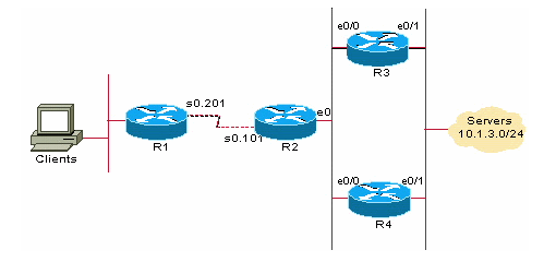
![]() (registered customers only) Show potential issues and fixes. To use the Cisco CLI Analyzer
(registered customers only) Show potential issues and fixes. To use the Cisco CLI Analyzer ![]() (registered customers only), you must be logged in and have Javascript enabled in your web browser.
(registered customers only), you must be logged in and have Javascript enabled in your web browser.
Eigrp metric modification
EIGRP metric