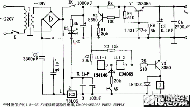
The following figure shows another power supply device with current protection made by TL431. It is mainly composed of two parts: voltage regulation and overcurrent protection. The working principle is as follows. The voltage regulation and expansion part is composed of a parallel regulator TL431, a widening transistor V1 and the like. TL431 and R4, Rw form an output voltage adjustable voltage regulator circuit, the adjustment range is 2.5 ~ 36V, the extension transistor V1 is connected to the emitter follower circuit, its emitter voltage follows its base voltage change, due to its emitter junction voltage drop It is about 0.7V, so the output voltage of this power supply is 1.8~35.3V. The overcurrent protection part is composed of an overcurrent detecting resistor Rx, an overcurrent detecting tube V2, a relay driving tube V3, a relay J, an IC1, an IC2, and the like. IC2 (78L06) provides +6V voltage for the relevant part (if you don't particularly value the volume and price, you can use 7806). When the circuit works normally, the voltage on the overcurrent detecting resistor Rx is small, which is insufficient for the overcurrent detecting transistor V2 to be turned on, V2 is in an off state, the collector has no voltage, and the input of the non-gate IC1-1 is low. The output is high, and the output of the non-gate IC1-2 is low. This low level is fed back to the input of IC1-1 via resistors R3 and R2 to lock it low. At this time, V3 is turned off, relay J does not operate, its contact K is in a closed state, the circuit works normally, and the working indicator light D3 emits light, indicating that the circuit works normally. When an overcurrent occurs in the circuit, the voltage across the overcurrent detecting resistor RX exceeds the turn-on voltage of the overcurrent detecting transistor V2, and V2 is turned on, and the collector and IC1-1 input are turned to a high level, IC1-2 The output also goes high, which is fed back to the input of IC1-1 via resistors R3 and R2, latching it high. This high level turns V3 on, relay J is energized, its contact K is disconnected, the voltage regulator circuit is powered off, and the working indicator D3 is off, indicating that the circuit is in an overcurrent protection state. However, IC1 is still in the power supply state, the input of IC1-1 and the output of IC1-2 are kept at a high level, V3 is continuously turned on, and the contact JK of relay J remains disconnected. After the overcurrent problem is solved, press the start button AN, the input end of IC1-2 is forced to be at the high level, its output becomes low, V3 is cut off, relay J is de-energized, its contact K is closed, IC1-2 output Low level, fed back to the input of IC1-1 via resistors R3 and R2, so that the state of relay J release remains unchanged, and the power supply can enter normal operation. The value of RX can be set according to the maximum output current of the required power supply. Select a resistor with sufficient power rating. Usb Connector,Micro Usb Sinking Connector,Usb 3.0 Solder Connector,Double Layer Usb Connector Dongguan Yangyue Metal Technology Co., Ltd , https://www.yyconnector.com