Follow WeChat Download Audiophile APP Follow the audiophile class related suggestion & n ... 1. Performance requirements of high-fidelity FM tuner Due to high-fidelity needs, the tuner has the following three points in terms of component selection and performance requirements:
1. High-frequency head The high-frequency head is the gateway of the tuner, and it has the characteristics of good selectivity, high sensitivity, low noise, strong anti-interference ability and high stability.
2. The performance of the intermediate amplifier in the intermediate frequency amplifier circuit is directly related to the selectivity, distortion, sensitivity, anti-interference ability of the whole machine and the accuracy of amplitude modulation suppression and tuning. It is required that the middle amplifier has higher limiting sensitivity, signal-to-noise ratio, amplitude modulation suppression ratio and lower distortion.
3. Stereo decoder Stereo decoder requires higher stereo separation and lower distortion. In order to improve the signal-to-noise ratio of the received weak signal, the stereo decoder is also required to have stereo noise control and high audio cut-off function.
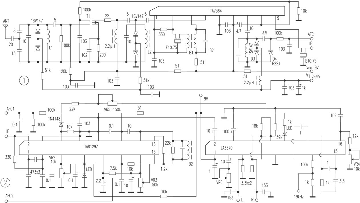
2. Production and debugging of high-fidelity FM tuner Electrically tuned high-frequency head The high-frequency head is composed of an LC resonant input loop, a field effect tube high-amplifier, and TA 7364, see Figure 1.
1) The LC resonant input circuit adopts the capacitive voltage-dividing impedance matching method. L1 does not need a tap, which facilitates the winding of L1.
2) The high-amplification stage is composed of high-frequency low-noise double-gate field effect transistor T1 and LC resonant circuit. The AGC control voltage is 4 ~ 0V, and the gain is ≥23dB.
3) The local oscillator, mixing frequency, and pre-discharge route consist of TA 7364P. The TA 7364P internally includes a double-ended balanced mixer, local oscillator, local oscillator buffer, broadband reverse AGC control, and intermediate frequency amplification. The wideband reverse AGC is most suitable for controlling the gain of the dual gate field effect high amplifier. Mixing frequency gain ≥ 11.5dB, intermediate frequency gain ≥ 24dB, AGC voltage 7.7 ~ 0.6V, typical working voltage 8V.
4) Both L1 and L2 can be self-made, choose ∮0.7mm enameled wire, L1, L2 inner diameter 4mm, around 6T, B1 series 10.7MHz intermediate frequency transformer, can be found on the waste two or three integrated circuit radio boards, domestic models TP501. VR1 selects the multi-turn tuning potentiometer for old color TV, and the resistance value can be 20 ~ 100kΩ.
5) The local oscillator frequency is affected by various factors and may cause frequency drift. An automatic frequency control circuit should be added. D4 is connected in parallel to the local oscillator circuit. The AFC voltage output by the intermediate amplifier circuit changes the capacity of D4 with the frequency deviation. The local oscillator frequency is finely adjusted within a certain range to keep the local oscillator frequency stable.
6) The high frequency head should be debugged with the cooperation of the instrument. Commonly used instruments include signal generator, frequency sweeper, frequency meter, etc. It is difficult to debug under amateur conditions, and it is often difficult to adjust to the best working point.
2. Intermediate frequency amplifier circuit The intermediate frequency amplifier circuit (see Figure 2) is composed of a high-performance FM integrated circuit TA8129Z, which includes 6-level limiting intermediate amplifier, radio detection, signal strength meter indication drive, bandwidth detection, frequency discrimination, low-pass filter, Circuits such as strong signal squelch and adjustable bandwidth squelch. The input limiting sensitivity is 33dBμ, the total harmonic distortion is ≤0.06%, the signal-to-noise ratio is ≥78dB, the noise suppression attenuation is 60dB, and the working voltage is 8V. ⑦The pin is the output terminal of the radio detection, which can be used for tuning instructions. The VR2 connected to the ⑤ pin is used for the adjustment of the radio detection sensitivity. ⑥The pin is the voltage output terminal of the signal meter. Generally, an ammeter is connected in series to indicate the signal strength. The output voltage varies between 0 and 6.8V with the input signal strength. This voltage can be used for stereo noise control and high-frequency cutoff of the stereo decoder. control. ⑨ DC voltage of 4.8V, when the frequency deviation, its voltage changes ± 0.7V, which can be used for automatic frequency control (AFC) of high frequency head. VR3 adjusts the amount of squelch attenuation.
The debugging of the intermediate frequency amplifier circuit is relatively simple. Input the signals of 10.7MHz and 80dBμ, connect the DC voltmeter to the ⑨ and {13} pins of TA8129Z, and adjust B2 so that the voltmeter indicates 0V.
B2 can be selected from a 7mm × 7mm TV set with a 38MHz mid-peripheral skeleton. It is made of ∮0.1mm enameled wire, with 5T in each of the three slots above, a total of 15T, and a loop capacitance of 24pF.
3. Stereo decoder The stereo decoder matched with TA8129Z selects LA3370.
The LA3370 is mostly used in high-performance tuners and mid-to-high-end car receivers. It includes stereo demodulation, stereo noise control, high-frequency cut-off control, and stereo / mono automatic selection circuit. Separation ≥50dB (at 1kHz), signal-to-noise ratio ≥78dB, distortion ≤0.05%, working voltage 9V.
The ⑦ and ⑧ pins of the LA3370 are connected to the output terminal of the TA8129Z signal strength voltmeter. When the received signal is weak, the stereo signal-to-noise ratio is greatly reduced, the noise is increased, and the output voltage of the signal meter of the intermediate amplifier circuit is reduced, added to ⑦, ⑧ The control voltage of the pin is also reduced, and the stereo noise control and high-frequency cutoff control are started, thereby changing the decoder's subcarrier demodulation level or controlling its separation, or automatically converting to mono, making the signal weak when the noise And the distortion is greatly reduced, this function is particularly conducive to remote reception.
There are three adjustment points in the LA3370, and VR4 adjusts the voltage-controlled oscillation frequency. Connect a frequency meter to the {13} pin, input a stereo composite signal, and adjust VR4 so that the output frequency is 19 kHz. VR5 adjusts the stereo noise and high-frequency cutoff control voltage, can receive a strong signal, adjust VR5 so that the voltage of ⑦ and ⑧ pin is 3V, and when static, the voltage of ⑦ and ⑧ pin should be 0V. Adjust the separation degree of VR6, short-circuit the capacitance between pin ③ and VR6, and adjust VR6 so that the DC voltage of pin ③ is 3V.
The filters at the output of L and R have a greater impact on the separation and distortion. The RC filter can only provide 36dB of separation with a distortion of ≥3%. The LC filter can effectively suppress the remaining 19kHz and 38kHz components, and can provide 50dB stereo separation with distortion ≤0.8%. However, the LC filter has the disadvantages of large size and high cost. Double T filter can also be used. fulfil requirements.
The tuner is best equipped with active speakers. Because the background noise of FM stereo audio is large, you do n’t need to use high-fidelity amplifiers and speakers, otherwise, it is counterproductive.
At this point, enthusiasts have a general understanding of high-fidelity FM tuners, that is, high-performance FM tuner, high-performance IF amplifier circuit, high-performance stereo decoder, the three are not a simple combination Instead, they are both related to each other and contain each other. A reasonable distribution of signal levels and control voltages can ensure that the three closely cooperate to give full play to their respective advantages and improve overall performance. 


![[Photo] High-fidelity two-channel power amplifier HSSH827](http://i.bosscdn.com/blog/20/06/41/51383214.jpg)
'+ data.username +'
[Photo] High-Fidelity FM Tuner
Interesting and informative information and technical dry goods
Create your own personal electronic circle
Lock the latest course activities and technical live broadcast
comment
Publish
[Photo] High-fidelity two-channel power amplifier HSSH827
Published on 2006-04-15 13:08 • 385 times read

