Follow WeChat Download Audiophile APP Follow the audiophile class related suggestion The circuit is shown in the figure. Set the input signal to be divided into 8 channels: U11 ~ U18, two CD4066 are needed. The control signal is sent by CD4017 ... Abstract: This circuit monitors noisy resistance values ​​or other harsh environments. In the connection of the secondary winding of the entire isolation transformer, the unknown resistance is reflected to the main ... Design of the transmission circuit in the remote ground sensor system 0 Introduction The wireless sensor network is a kind of RGS system (remote ground transmission ... Capacitor-based electromagnetic fully isolated DC power transmission circuit Keywords: Electromagnetic interference switching power supply Abstract: This paper proposes ... Double-channel long-line transmission circuit With the development of electronic technology and the emergence of digital sound sources, people's attention ... High-fidelity FM audio signal transmission circuit When watching TV late at night, you usually have to lower the volume so as not to affect the rest of others, which may make it impossible to hear the TV sound. If there is a circuit that can transmit TV sound signals to the surrounding space, and then use FM radio to receive it can solve this problem. The circuit is shown in Figure 1. 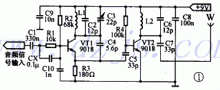
In the circuit of Figure 1, VT1 and its peripheral circuits form an oscillation circuit with an oscillation frequency of approximately 98 MHz. R1 and Cx are audio pre-emphasis circuits that are used to improve the frequency response of audio signals and improve sound quality.
Both L1 and L2 are made of 1mm enameled wire wound around 10 turns on a 5mm skeleton, and the length can be elongated to about 11mm, as shown in Figure 2. 
If the circuit does not work properly, it is necessary to check whether the contact between the component pins and the wiring is good, especially the pins of the transistor must not have virtual soldering. Use tweezers to short-circuit the two ends of L1. If the current of the whole machine changes, it means that the circuit has started. If the current does not change, check whether the resonant capacitor C3 has been connected and adjust its capacitance until the circuit starts to oscillate. 


![[Photo] Frequency-stabilized FM signal transmission circuit](http://i.bosscdn.com/blog/20/06/41/5205255320.gif)
![[Photo] High-fidelity head magnifying board](http://i.bosscdn.com/blog/20/06/41/513653757.gif)
'+ data.username +'
[Photo] High-fidelity FM audio signal transmission circuit
Interesting and informative information and technical dry goods
Create your own personal electronic circle
Lock the latest course activities and technical live broadcast
comment
Publish
Multi-signal patrol detection transmission circuit
Posted at 2010-12-06 13:29 • 312 times read
Resistance monitoring of transmission circuit through isolation layer
Posted at 2010-11-19 10:01 • 244 times read
Design of transmission circuit in remote ground sensor system
Published on 2010-01-12 10:53 • 245 times read
Electromagnetic fully isolated DC power transmission circuit based on capacitance
Published on 2009-11-13 19:00 • 330 views
Double-channel long-line transmission circuit
Posted on 2008-12-22 02:30 • 221 times read
[Photo] Frequency-stabilized FM signal transmission circuit
Posted at 2006-04-15 20:52 • 265 times read
[Photo] High-fidelity head magnifying board
Published on 2006-04-15 13:06 • 1219 times read