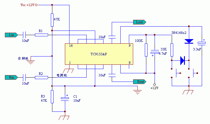
DIY of TC9153AP volume control circuit Since Toshiba ’s electronic file did not directly give the application circuit of TC9153, I had to bite the bullet and gnaw the file, and finally found the reason: the original "Application" article made a mistake of the ground wire, and no wonder he also appeared "dudu "," Whisper "impulse noise. Now I draw the available circuit diagrams as follows for friends who do not have DIY success to make and refer to. In addition, I suggest that it is best to place the circuit at the front input when DIY, because the circuit overload capacity is poor. The circuit diagram after my modification is as follows: The principle of this IC is a potentiometer, so R1 and R2 resistors as shown in the above figure can be connected in series at the input end. According to my experiment, when the resistance is 47K, the distortion will appear when playing with a large dynamic CD. When it is increased to 68K, the distortion disappears, so DIYER can choose the size of the resistor according to the actual situation. My post-stage magnification is 96 times. During the night test, the speaker can hardly hear noise at one meter, and the IC volume control effect is also excellent. Follow WeChat Download Audiophile APP Follow the audiophile class related suggestion 


'+ data.username +'
[Photo] DIY of TC9153AP volume control circuit
Interesting and informative information and technical dry goods
Create your own personal electronic circle
Lock the latest course activities and technical live broadcast
comment
Publish
