1W power FM radio transmitter Idle is also idle, it is better to be a 1W power FM radio transmitter The production of this FM transmitter is very special. No need to engrave the circuit board. Second, there is no circuit diagram. It ca n’t be used. Third, if you do n’t solder the wrong one, it will be OK. How can the power reach 600MW or more? Power component pin Description: 1: The oscillation stage uses the "Colpitts" oscillation circuit, don't look at it is also an LC oscillation, but this LC is not the other LC, can not be confused with the stability of other FM circuits, the case of running the frequency when the hand touches or the person is close to the point It's nothing. It seems to be all right? As a final reminder, do n’t interfere with other people ’s normal listening. It ’s best to adjust the frequency beyond 88-108MHZ. After all, 1W of FM power cannot be considered small (generally the standby mobile emergency radio station of FM radio stations in small and medium cities is about 10W), otherwise The government will soon trouble you. Follow WeChat Download Audiophile APP Follow the audiophile class related suggestion
Speaking of the production of transmitters and the like, there are the most bugs. The expanded version is said to have hundreds of them in FOLLOW ME RADIO. Haha, is it true?
But waiting for his words, who knows that it will be the year of the monkey? Far water can not save near thirst, it is better to self-reliance and start now.
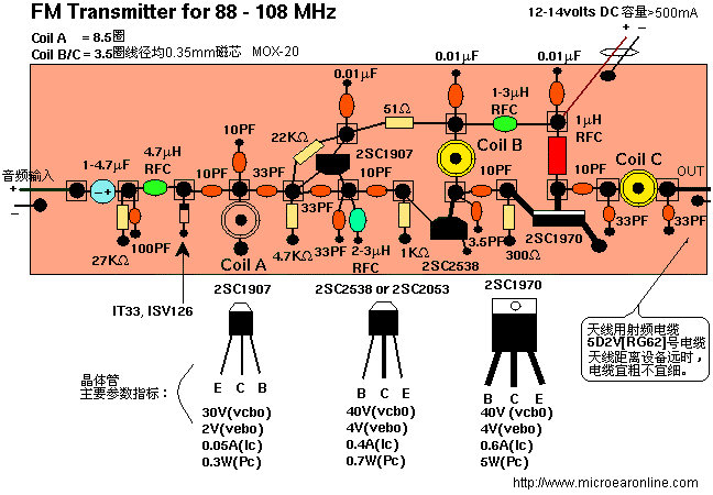
Without further ado, you can now see the final assembly as shown below (the principle is not mentioned, is it faster in one step?) 


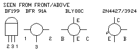
 Power component pin
The oscillation is completed by a tube of 2SC1907. COILA and the 10PF above it and the left side determine the basic frequency of the circuit. Audio modulation is done by a varactor diode, and a starting voltage can be added to it through a 47-270K resistor, the linearity will be better. The "Colpitts" oscillation circuit is stable, thanks to the 33PF in the figure, which relatively isolates the critical LC part from other circuits.
2: After the C2053 buffer frequency selection C1970 power amplifier, the output impedance of the C1970 is about 50 ohms at 1W. Oh, the impedance matching circuit is saved. The following COILC and capacitors are "passband filters" to avoid clutter that is too large for others to trouble you.
3: How to do circuit board PCB? See the squares in the center of the assembly drawing? It is actually cut into small pieces with a double-sided PCB board. One side is welded to the motherboard for fixing, and the other side is lap welded. There are not many parts anyway, right?
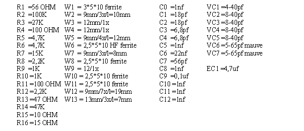
4: Don't make mistakes for the parameter values ​​of all parts. Welding is done when the legs are short enough to use. Small ceramic capacitors should use high frequency red dots. The other parameters of green are not accurate enough. After welding, check that there is nothing wrong and you can power on.
Ten million, remember to load the end of the antenna with a flexible cord before powering on, or it will burn out after a while in C1970! It is best to have a power meter or any other instrument to adjust it. If not, find a small lamp that requires a low voltage and low current of 1.25V75MA. The +-pole is connected to a 60CM length of wire and is rounded near the transmitter. The commissioning is relatively simple, with direct power on, the total current should be within 300MA, the bulb is also lit, basically OK, all circuits need to be adjusted only COILB and C, the adjustment target, the small bulb is the brightest.
The reason why this circuit is reliable and easy to succeed is that its own circuit has basically determined the general parameters of the device-even if only the adjustable inductances B and C are needed, after the circuit is installed, if there is no wrong winding and before adjustment, the circuit It can also output radio frequency outwards. The difference between adjusted and unadjusted lies in the size of power and clutter.
In addition, the antenna frame should be connected with a cable when it is far away from the circuit. 


'+ data.username +'
[Photo] FM radio transmitter with 1W power
Interesting and informative information and technical dry goods
Create your own personal electronic circle
Lock the latest course activities and technical live broadcast
comment
Publish
[Photo] Self-made low-power FM radio transmitter
Published on 2006-04-15 20:47 • 738 times read
