In the first blog post of this series, we learned how FPGAs were introduced into the driver architecture. Now, let's take a look at some of the challenges of using an FPGA in an industrial drive/servo architecture, and how the new functions of a system-on-chip (SoC) operating in the form of a COTS MCU can be changed with FPGAs for industrial drives. Cost effective model. Many industrial inverter and servo vendors rely on field-programmable gate array (FPGA) or ASIC technology for a long time to perform functions not supported by commercial off-the-shelf (COTS) products such as 32-bit microcontrollers (MCUs). However, to support position sensor feedback or incremental-accumulation filtering, FPGAs and ASICs added to software programmable controllers will increase system cost and development complexity. Shouldn't we ask: Is the function being placed into the FPGA a real change for the driver? Is it a standard practice for every drive manufacturer to include these features? In short, are these FPGA gates that are used to achieve the required functionality at a price that is too high and have become a bargaining chip in the industrial drive industry? While FPGAs are reprogrammable and are believed to provide system adaptability and better system performance, they have certain drawbacks relative to current MCUs used in industrial drive applications. Developers should measure the required specialized engineering skills, overall project effort, and total system cost. Many of the drive systems being developed maintain a C-programmable microcontroller or microprocessor combined with an FPGA. The C code generation and debugging development environment for this processor is well known and necessary. Introducing an FPGA into this system now requires an additional development process and toolset. Although these tools have made some progress in ease of use when it is publicized, it is not the same group of engineers who usually develop MCU C code and develop FPGA VHDL code. The VHDL coding style and development process are very different from the MCU software development and require special engineering resources. In addition, it is precisely the FPGA developers who must be low-level and system-level experts in the hardware IP they perform. For example, they not only need to know how to implement VHDL for a BiSS host, they need to understand the BiSS protocol because they need to verify that their FPGA appliances meet the requirements of the BiSS sensor. This specialized engineering skill is not available to every motion control or inverter manufacturer, and of course it does not play their unique role in motion and motor control performance. Is it simpler to use only one microcontroller that supports BiSS encoders by itself? From a development perspective, managers need to think of FPGA creation as a custom development. Their development team has additional ownership of the product features of the FPGAs on the market and is responsible for the characteristics of these products. If VHDL is not properly coded, they can't turn to the FPGA vendor; they can only find the cause of the problem and find a remedy to solve the problem. When you compare VHDL with a model that uses COTS MCUs, the customization responsibilities associated with FPGA development far exceed the gate design work within the FPGA. Printed circuit board (PCB) effects, MCU gate/register interfaces, software abstraction, and overall system integration workloads are all non-standard, that is, they are not readily available solutions. See Figure 1 for details. In addition to development, this model has additional engineering complexity in terms of user support, product maintenance releases, and long-term quality consistency with the release or modification of new connectivity components. Is it easier to use a standard MCU with these features and the vendor is responsible for the entire product solution (hardware, software, tools, and design)? Figure 1: Comparison of EnDat development between FPGA and driver SoC In addition, perhaps the most obvious point is the impact of additional components on the bill of materials. The cost of FPGAs is by no means limited to the impact on unit price. The FPGA device will require additional PCB area, as well as the pins required for MCU docking and power. These costs are unavoidable when running with an FPGA, but these overheads are not necessary when these features already exist on the drive SoC MCU. In several cases, we observed that the FPGA itself requires additional, more complex power circuits than the drive SoC device. In addition, the execution FPGA introduces redundant gates into the system, such as the register interface to the MCU, and an external analog-to-digital converter (ADC) interface that implements phase current and voltage sensing. A driver SoC includes a built-in high performance ADC for drive applications and does not require this additional logic. Therefore, using a single COTS to drive an SoC can have many opportunities to reduce overall system cost relative to an MCU with an additional FPGA fabric. The 2000TM MCU supporting DesignDRIVE technology is a COTS MCU; it provides a higher level of drive system integration with the overall product concept, benefiting drive developers by reducing the need for specialized engineering talent, saving development time and simplifying system costs. In the next article in this blog series on Drive Control Architecture, I will focus on how the Spot C2000 DelfinoTM MCU Industrial Drive SoC handles functions that have traditionally been performed by an FPGA: Fast Torque Loop Calculation, Modulated Incremental-accumulated ADC signal filtering, high performance PWM, PWM protection, and docking with high performance position sensors. Manual Motor Starter,Motor Starter,KNS12,China Motor Starter Wenzhou Korlen Electric Appliances Co., Ltd. , https://www.korlen-electric.com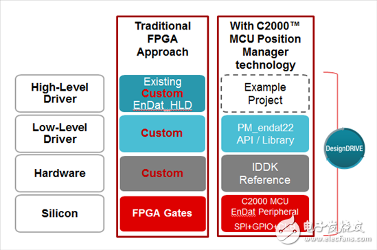
How does FPGA introduce an industrial drive architecture?
The Manual Motor Startor is Korlen electrical appliances anther products. manual motor startor overload relay is in main circuit of long time working. It is used to protect AC three-phase asynchronous motor against overload and open phase. It conformity with IEC947-4, VDE0660,GB14048.4 standards . As a motor starter switch in china ,korlen will do the best electrical motor controls for customers.
The Manual Motor Startor related products have the following: Thermal Relay , AC Contactor, led light, Circuit Breaker etc.