When the MCU CPU is processing an event A, another event B is requested to request the CPU to quickly process (interrupt occurs); the CPU temporarily interrupts the current work, and goes to process event B (interrupt response and interrupt service); wait for the CPU to event After B is processed, return to the place where the original event A was interrupted and continue to process event A (interrupt return). This process is called interrupt. When you are washing, suddenly the phone rings (interruption occurs), you temporarily interrupt the laundry work, turn to answer the phone (interrupt response and interrupt service), wait for you to pick up, then come back to continue the laundry (interruption return), this A process is an interruption. The microcontroller interrupt also has the concept of interrupt priority and interrupt nesting, but not all microcontrollers support both functions. The interrupt priority level is different. Different interrupts have different priority levels. If two interrupts are generated at the same time, the microcontroller will respond to the interrupt with higher priority. Interrupt nesting means that a new interrupt is generated in the interrupt response. The microcontroller can suspend the current interrupt program execution to respond to the new interrupt. After the new interrupt program is executed, the current interrupt program is executed. General interrupt nesting is a high-priority interrupt that can be inserted into a low-priority interrupt responder. A peer or low-level interrupt cannot be inserted into the current interrupt responder. Step 1 Save the main program site and execute the interrupt 1 service program. Step 2 save interrupt 1 service program site, execute interrupt 2 service program Step 3 resume interrupt 1 service program site, continue to execute interrupt 1 service program Step 4 restore the main program site, ready to continue to execute the main program, there is a new interrupt can not continue to execute the main program Step 5 save the main program site, execute the interrupt 3 service program Step 6 restore the main program site, ready to continue to execute the main program, there is a new interrupt can not continue to execute the main program Step 7 save the main program site, execute the interrupt 4 service program
This aluminum alloy ladder is light, handy, and easily portable. It is equipped with the hook, the D shaped anti-skid ladder rung, as well as the anti-skid tape of telegraph pole.
Our working platform is aluminum alloy frame style. The item number is 22251. This product can be used on the tension support for balance line, high altitude crimping, and other operation. When the load is excessive, the number of lifting rope should be increased and a test is taken. This rope is supposed to fasten the bottom material.
Rotary Hammer Drill,Electric Tool,Portable Impact Wrench,Electric Angle Grinder,Chain Saw MARSHINE , https://www.puller-tensioner.com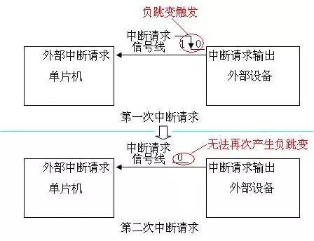
Figure 1 The peripheral can only generate one interrupt request signal. The schematic diagram of the interrupt request signal of the external device is modified. The original output is changed from high to low when the interrupt is needed. Now the output is changed from high to low, after a short period. After the time, I change from low to high, so that each time an interrupt is required, a negative transition trigger signal can be output to the microcontroller. 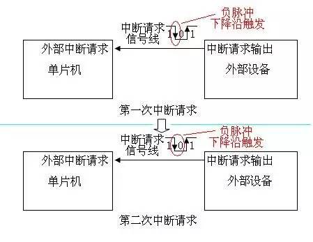
Figure 2 The peripheral can continuously generate an interrupt request signal. Figure 1 or an external device provides an interface through which the microcontroller can perform an interrupt clear operation on the external device. The interrupt clear operation can restore the interrupt request output of the external device to a high value. . 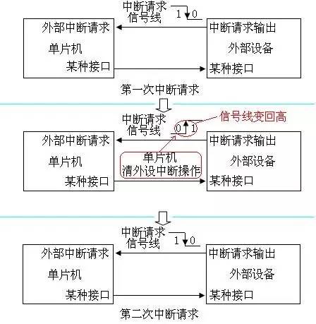
Figure 3 Peripherals can continuously generate interrupt request signals. Figure 2 External interrupt triggers There are also some special methods, such as external pulse width measurement, external pulse counting, etc. These methods are all extended in the first few basic trigger modes. The external pulse width measurement means that when the interrupt signal line jumps, an internal timer is started. When the next interrupt signal line jumps, the pulse width is obtained by the timer and the timer is restarted. These methods are rarely used, and Do it in detail. The internal interrupt refers to the interrupt function generated by the function module inside the MCU. As long as the function module that can work independently in the peripheral of the MCU will provide the interrupt function, common internal interrupt types include clock Timer, serial port UART, analog-to-digital conversion ADC and so on. The internal interrupt workflow is not much different from the external interrupt, except that the interrupt request signal is transmitted inside the microcontroller. The interrupt signal is not the level state on the pin, but the corresponding flag in a register, usually when some internal When the interrupt generates an interrupt request, the corresponding flag will be set to 1, and the flag will be cleared to 0 when the CPU responds to the interrupt. 
Figure 4 Schematic diagram of internal interrupt triggering There is no uniform standard for the processing of interrupt flag bits by the MCU. The specific convention method depends on the MCU documentation. Most of the flag bits are 1 with interrupt generation, but there are a few microcontrollers that have a flag bit of 0 and an interrupt is generated; some microcontrollers write to the interrupt flag bit what the CPU writes to rewrite what, and some of the rules must be written by 1 or write 0 to achieve the clear operation, there are a few that just read the interrupt flag will automatically clear the flag. If the MCU does not want to be triggered by an external interrupt, it will be fine to connect the pin for connecting the external interrupt trigger signal to the voltage state that will not trigger the interrupt, but the internal interrupt cannot change the internal connection, so the MCU can select whether the interrupt can be selected. Divided, there will be related registers in the internal selection, through the control flag inside the developer can decide whether to use the interrupt according to the actual situation. Usually there is a total control bit in the MCU. This bit can control the on and off of all interrupts. Then each interrupt has its own independent control bit to determine its own on and off. If you want to use an interrupt, you need to The total interrupt switch and the corresponding interrupt switch are both turned on. When the MCU has an interrupt signal generated, the corresponding interrupt will be triggered. Different interrupt sources will require different response methods. That is to say, when different interrupts are generated, the MCU program needs to respond differently according to different interrupt sources. Is the interrupt service program. If the UART receives new data to generate an interrupt, it should be the UART interrupt service routine to read the data back and process it. If the interrupt is generated by the ADC conversion completion, the ADC interrupt service routine needs to read the data back and process it. If you need to clear the interrupt flag action, it is usually done in the interrupt service routine. Different interrupt sources need corresponding interrupt service programs. In actual development, not all interrupts will be used. In order to save program code space, developers will only write the interrupt service program they want to use. There are some interrupts that do not have corresponding interrupt service routines. If such an interrupt is triggered, the microcontroller program will run an error. The separate interrupt control bits will be used in the front, and these control bits will be turned off, and the corresponding interrupt will not be used. trigger. When the microcontroller starts power-on, if the register control flag bit that controls whether the interrupt is turned on is turned on, the interrupt may be triggered by mistake. If the interrupt does not have the corresponding interrupt service routine, the program will run away. Therefore, when the microcontroller is powered on, the flag bits in these registers are automatically turned off to avoid false triggering. The interrupt service program is part of the MCU program. The specific content is determined by the developer. The position of the interrupt service program is not fixed in the MCU program. When the MCU interrupt is triggered, the MCU needs to know where the interrupt service program is located. Executing it, the microcontroller solves this problem by interrupting the jump table (interrupt vector table). Although the size of the interrupt service routine and the location in the entire program will not be fixed, the program will be fixed in the size of the interrupt service routine and the entire program as long as it is burned into the microcontroller system. If we make some conventions for the space allocation of the microcontroller program, an absolute fixed address is specifically allocated to the interrupt. When the program compiles, the start address of the interrupt service routine (or the instruction that jumps to the interrupt service routine) is filled in. Absolute fixed address space, when the interrupt is generated, the MCU first reads the contents of the absolute fixed address, and can jump to the interrupt service program according to the read content. 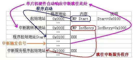
Figure 5 Interrupt Response Schematic A simple microcontroller provides a limited number of interrupts. To simplify the program, each interrupt is assigned an address space for the address of the interrupt service routine. This method is actually not bad, just microcontroller technology. The development has now encountered bottlenecks, high-end single-chip microcomputers are becoming more and more complex, so some professional manufacturers began to cooperate to share technical resources. For example, ARM uses their technical advantages in the CPU architecture system to provide CPU cores for other vendors. Other vendors are The CPU core of the ARM core adds function modules, and most of these function modules support interrupts. 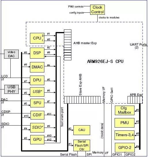
Figure 6 ARM core MCU architecture diagram The peripheral functional modules of different MCUs designed by different manufacturers on different CPU cores will be different, so the types and numbers of interrupts are different, and the CPU handles the interrupts in the same way. If the continuation of a simple microcontroller to allocate an address space to each interrupt is obviously a problem, the CPU can not know how many types of interrupts need to be supported, and which interrupts correspond to which modules, so another interrupt processing method will be used. The interrupt addresses all point to the same one, and all interrupts are numbered sequentially. When the interrupt is generated, the CPU will tell the interrupt service routine what the current interrupt number is, and then the interrupt service routine responds according to the interrupt number. 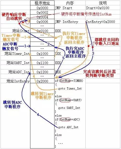
Figure 7 Common interrupt entry interrupt response flow chart 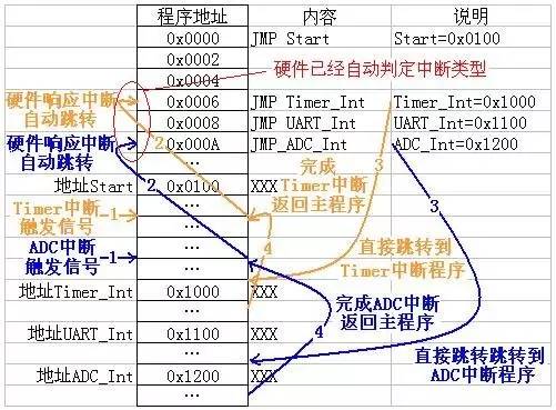
Figure 8 Independent interrupt entry interrupt response flow chart All interrupts use the same interrupt vector address and then determine the interrupt class by interrupt number. Although the general CPU core interrupt can not directly correspond to the interrupt vector address, but it interrupts the processing flow and A microcontroller with an independent interrupt vector table will find that the response speed of the interrupt will be slower. A single-chip microcomputer with an independent interrupt vector table can directly enter the interrupt program as long as a jump instruction, and the microcontroller without the independent interrupt vector table needs to jump to the interrupt common input first, and then determine the interrupt category by code, and then determine the interrupt category before jumping. Go to the real interrupt routine. The C language code will make this situation worse, so if the microcontroller does not have an independent interrupt vector table, it generally uses the method of assembling table lookup to speed up the interrupt response. 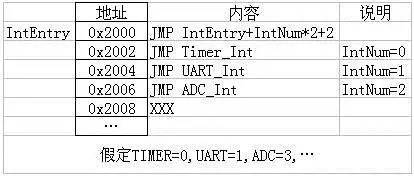
Figure 9 Assemble interrupt fast jump table interrupt program execution is completed and then return to continue to execute the main program, so that the interrupt does not change the running state of the main program, so the interrupt response needs to save the current running state information of the program, such as program running Information on where to go, the status of the current CPU status register, and so on. When the interrupt program is executed, you can use this information to restore the CPU status register to its original state and return to the original program to continue execution. Different MCUs will handle this differently. One is completely done by hardware and does not need to be managed by the program. The other is to save the status information in a specific location with the corresponding instruction, and then use it when returning. The command returns to its original state. 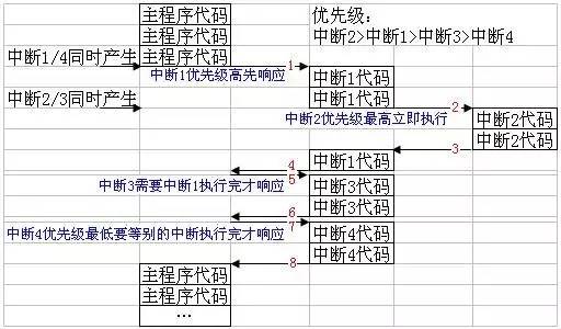
Figure 10 Schematic diagram of interrupt nesting
