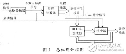
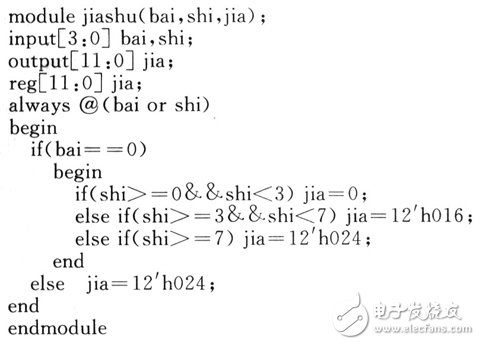
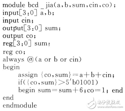
FPGA (Field Programmable Gate Array) is a high-density programmable logic device that supports system programming and can implement different logic functions by writing different configuration data. The use of FPGA to design electronic systems has obvious features such as short design cycle and easy modification. It is especially suitable for scientific experiments, prototype development and small batch production of electronic products. In this paper, for the FPGA device, ETA tool software Max+P1usII is used to design a taxi meter, which can display the mileage of taxis and the expenses payable by passengers in the form of decimal numbers. It has certain practical applications. value. The taxi meter to be designed is required to display the mileage and the cost payable by the passengers, wherein the mileage is accurate to 0.1km, and the passengers pay the exact amount to O. 1 yuan, the display must be in decimal form. The taxi charging standard is: starting price is 6 yuan, mileage is within 3 km, starting price; when the mileage is between 3 and 7 km, it is 1.6 yuan per driving 1 km; when it is more than 7 km, every driving 1 km increased by 2.4 yuan. The design of the system can be built with discrete components, or can be designed by single-chip microcomputer, and designed with programmable FPGA. It has obvious features such as short design cycle and easy modification, and with the rapid development of programmable logic devices and EDA software. More and more electronic systems are designed using FPGAs. Once the system reaches a certain mass production scale, it is easier to convert into an ASIC chip design. Therefore, design a taxi meter based on FPGA. In the EDA tool software MAX+plusII, the system uses the combination of hardware description language Verilog HDL and schematic design to design each module, and finally each module is composed of the whole system. The taxi can display the mileage of the journey, which can be generated by the rotation of the wheel and then counted by the counter. Assume that a taxi generates a pulse every 2 m. Because the mileage is accurate to O. 1 km, which is 100m, so a new pulse signal is output every 50 pulses, which is called 100 m pulse signal. As the clock signal of the mileage counter, it can be divided by a 50-meter counter. . The mileage counter can be implemented with a three-digit BCD code counter that can display up to 999. The previous two are integers, the third is decimal, which means the maximum mileage is 99.9 km. Because the taxis are active in the urban and suburban areas, the three BCD code counters can count the mileage. Each time the mileage counter counts 1 km, it also periodically outputs a pulse signal, called a 1 km pulse signal, which can be realized by a certain combination circuit. The core part of the system is how billing is implemented. Here, we need to design a BCD code adder. Based on the starting price, according to the mileage, according to the billing standard, for each additional 1 km plus a unit price, the unit price can be generated by Verilog HDL. The overall design block diagram of the system is shown in Figure 1. The Verilog HDL source code for the unit price generation module is as follows: The input signals bai and shi are the two-digit integer mileage output by the mileage counter. The output signal jia is the unit price generated according to the charging standard, and is output in the form of three-digit BCD code. The previous two digits are integers, and the third digit is a decimal number. That is, when the mileage is within 3 km, jia=0; when the mileage is between 3 and 7 km, jia=016 (1.6 yuan); when it exceeds 7 km, jia=024 (2.4 yuan). The advantage of using Verilog HDL to write programs to implement module functions is that when the taxi's billing standard changes, it is easy to rewrite the program to complete the new design, which is much more convenient than the hardware circuit modification. The key advantages of using the Verilog HDL to implement module functionality. A three-bit BCD code adder is used in the system to add three decimal digits. The result of the adder output is the cost payable by the passenger. Here, the previous two digits are integers, and the third digit is a decimal number, that is, the maximum can display 99.9 yuan. The three-bit BCD code adder is formed by cascading three one-bit BCD code adders. A BCD code consists of four binary digits. The addition of a four-digit binary number produces a number greater than 9, which must be properly adjusted to produce the correct result. The Verilog HDL source for a BCD code adder is as follows: The simulated waveform of a BCD code adder module and the generated module symbols are shown in Figures 2 and 3. Best Rechargeable Vacuum Cleaner,Rechargeable Hand Vacuum Cleaner,Small Rechargeable Vacuum Cleaner,Cordless Rechargeable Vacuum Cleaner Ningbo ATAP Electric Appliance Co.,Ltd , https://www.atap-airfryer.com

