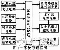
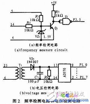
After the helicopter took off, the generator was powered by the aircraft engine to provide a stable 115 V/400 Hz AC power for the aircraft. All power-borne airborne equipment power supplies are directly used at 115 V/400 Hz or are used after being converted. Therefore, the stability of this power supply is directly related to the lifespan and flight safety of airborne equipment. The airborne control protection box mainly monitors the voltage and frequency signals of the generator network. When overvoltage, undervoltage, overfrequency, underfrequency, overfrequency, underfrequency and differential current exceeds the standard in the power grid, the safety time is timely. Cut off the main circuit and the generator excitation circuit and switch it to the standby power supply to effectively protect the airborne equipment and flight safety. The control protection box consists of AT89S52 microcontroller system, power supply circuit, reset circuit, voltage detection circuit, frequency detection circuit, differential current detection circuit, main circuit contactor control circuit, 27 V DC power supply circuit, generator excitation control circuit and sound alarm circuit. Composition, as shown in Figure 1. The power supply circuit provides +5 V DC power for the microcontroller and the 27 V DC power supply circuit provides 27 V for the contactor. The working principle is as follows: The voltage detection circuit samples the on-board AC power supply. After sampling, it is converted into DC power. After the DC power is converted by the AD, it is converted into a digital signal and compared with the data stored in the microcontroller to determine whether the airborne AC has overvoltage or undervoltage. When overvoltage or undervoltage occurs, the delay is fixed. The control signal is sent after the time, the main circuit contactor and the generator excitation circuit are cut off, and an audible alarm signal is issued at the same time; the frequency detection circuit converts the onboard AC into a frequency-dependent pulse signal, which is converted into a frequency signal after counting. When over-frequency, over-frequency, under-frequency and under-frequency faults occur, the microcontroller sends a control signal to cut off the main circuit contactor and the generator excitation circuit, and simultaneously sends an audible alarm signal; the differential current detection circuit detects the three-phase AC Power supply, when the three-phase power supply current difference reaches a certain value, the microcontroller sends a control signal to cut off the main circuit contactor and the generator excitation circuit, and at the same time issue an audible alarm signal. The hardware of the control protection box is composed of a single-chip microcomputer system, a power supply circuit, a frequency detection circuit, a differential current detection circuit, a voltage detection circuit, a power supply control circuit, and a generator excitation circuit. The AT89S52 single-chip microcomputer system adopts the minimum single-chip computer system and the button reset design. The specific circuit is not described in detail. The other six parts of the circuit are mainly introduced. 2.1 Frequency Detection Circuit and Voltage Detection Circuit Frequency detection circuit, as shown in Figure 2 (a). It mainly implements the detection of the frequency of the on-board AC power supply. When the on-board AC power supply experiences over-frequency, over-frequency, under-frequency and under-frequency faults, the airborne generator excitation circuit and the airborne equipment power supply circuit are cut off within a specified time. . Take 5th or 14th and 4th pins of the onboard AC power input control box and the AC power flows through the current limiting resistor and the 1.5 V regulator. When the instantaneous value of the AC power supply voltage is higher than 1 .5 V, the voltage regulator reverse conduction to form a 1.5 V voltage, the transistor conduction output 0 V voltage, after the NAND gate shaping the output logic high "1", input SCM P3.5; When the exchange When the power supply voltage is lower than 1.5 V, the regulator tube is conducting. The transistor turns off the output voltage of 5 V. After the NAND gate is shaped, it outputs a logic low level “0†to input the P3.5 port of the single-chip microcomputer; therefore, each one AC cycle, P3.5 mouth to get a high level. The AT89S52 microcontroller counts the pulse number of P3.5 port in a certain period of time. The power frequency of the on-board AC power supply is calculated and the frequency detection is completed. 2500 Puffs Disposable ecig have a completely enclosed design, reducing the need for charging and replacing cartridges. The no-charge design also reduces the occurrence of faults. It is understood that with rechargeable e-cigarettes, each cartridge needs to be charged at least once and the battery efficiency is extremely low, while the design of disposable ecig can solve this problem very well. 2500 Puff Disposable Vape,Disposable Mini Vape Stick,Puff Disposable Vape,Mini Puff Disposable Vape Shenzhen E-wisdom Network Technology Co., Ltd. , https://www.healthy-cigarettes.com
A type of helicopter airborne control protection box is a product of the 1980s, and the control circuit is implemented by an analog circuit constructed by discrete components, which has the disadvantages of large volume, large measurement error, and the like. This paper adopts AT89S52 microcontroller to design a digital airborne control protection box. The digital airborne control protection box improves the accuracy of measurement based on the protection function, shortens the protection time, and increases the sound alarm function. 
