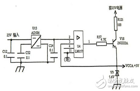
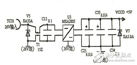
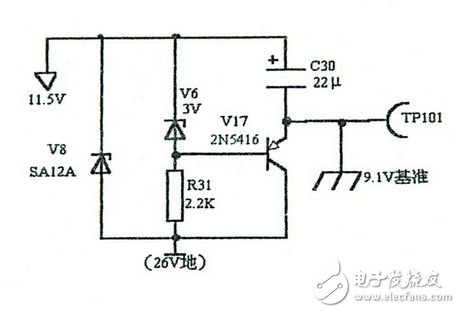
The tracking system is an important part of the infrared missile product. It is mainly used to measure the orientation of the target and provide tracking instructions for the tracking valve to make the gyro precession. The marker tracks the target so that the target is kept near the optical axis of the marker. The tracking system adopts DSP digital signal processing technology, which enables the target to be more accurately positioned and tracked. The anti-jamming technology is stronger, the range target is farther, and the combat power is stronger. The infrared missile has further development, and the tracking system carries out the missile loading. The performance of the computer has improved the performance of the missile weapon system. The tracking system receives the four signals and the reference signal from the positioner, measures the orientation of the target and generates a correction signal required by the positioner valve, that is, the tracking command, and after the signal is amplified, drives the positioner valve to precession of the gyro. Keep the target at the center of the instantaneous field of view of the marker. At the same time, the tracking system outputs the target to the other components of the missile, and captures the acoustic signals H, F, DIS, ATEL and other signals. Output tracking, guidance power amplifier turn-on signals PDIS1, PDIS2; generate safety distance timing signals SD1, SD2, detonate signal SD3; generate automatic gain control signals AGC1, AGC2, AGC3, and the like. Power source section There are three power supplies, two types: analog circuit power supply, digital circuit power supply. Among them, the analog power supply has VCCA+5V DC power supply and 9.1V reference power supply; the digital power supply has VCCD+5V DC power supply. VCCA+5V DC power supply VCCA+5V DC power supply is shown in Figure 2. U13 is a 23V to 5V DC-DC converter, which serves as the reference voltage for the DSP internal analog-to-digital conversion circuit and digital potentiometer. U4, R37, V18, R121 and other components form a current-expanding circuit to increase the load capacity. C12 and C52 are filter capacitors. During normal operation, the voltage at the negative terminal of V9 is 14.1V, the voltage at the positive terminal is 9.1V (both at 26V power ground), and the +5V power supply is output from the V18 emitter. Figure 2 VCCA + 5V DC power supply circuit schematic 2VCCD+5V DC power supply VCCD+5V DC power supply is shown in Figure 3. U3 is a DC-DC converter. It has a transformer inside, which converts 26V to 5V. At the same time, it isolates the 5V digital power supply from the analog power supply and supplies power to DSP, optocoupler and other devices. . T1 is an inductive coil, which can improve the anti-electromagnetic interference performance of the circuit; C13, C23, C33, C34 are filter capacitors. V5 and V7 are transient suppression diodes. They do not conduct during normal operation. When the device power or tracking system power supply is greater than its maximum allowable peak voltage, the diode breaks through the short circuit to protect the tracking system. Figure 3 Schematic diagram of VCCD + 5V DC power supply circuit 9.1V reference power supply The 9.1V reference power supply is shown in Figure 4. The input voltage is 11.5V, and the voltage regulation voltage of the voltage regulator V6 is 3V. Therefore, the base voltage of the transistor V17 is about 11.5V-3V=8.5V. After the power is stabilized, V17 The voltage difference between the base emitters is -0.6V, so the emitter output voltage is 8.5+0.6=9.1V, and C30 is the filter capacitor. The role of the 9.1V reference power supply is to make the four-way target signal pass smoothly. Figure 4 Schematic diagram of 9.1V reference power supply circuit Laptop Computer,Core I5 Laptop,Metal Slim Laptop,Fhd Laptop C&Q Technology (Guangzhou) Co.,Ltd. , https://www.gzcqteq.com

