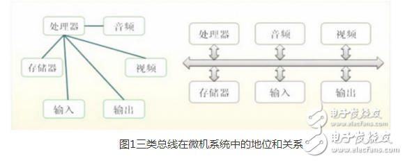
Bus base Bus is a common communication trunk that transfers information between various functional components of a computer. It is a transmission harness composed of wires. According to the type of information transmitted by the computer, the bus of the computer can be divided into a data bus, an address bus, and a control bus. Used to transmit data, data addresses, and control signals, respectively. The bus is an internal structure, which is a common channel for the CPU, memory, input and output devices to transmit information. The various components of the host are connected by a bus, and the external device is connected to the bus through a corresponding interface circuit, thereby forming a computer hardware. system. In a computer system, a common path for transferring information between various components is called a bus, and the microcomputer is connected to each functional component by a bus structure. 2. How the bus works When the bus is idle (other devices are connected to the bus in a high-impedance state) and one device is to communicate with the destination device, the device initiating the communication drives the bus to issue the address and data. Other devices connected to the bus in a high-impedance state receive the data on the bus if they receive (or can receive) address information that matches their own. The transmitting device completes the communication and gives up the bus (the output becomes high impedance). 3. Classification of the bus A. By function and specification. Figure 1 The status and relationship of the three types of buses in the microcomputer system (1) Chip Bus (C-Bus), also called component bus, is an information transmission path that connects various chips together to form a specific function module (such as a CPU module). Its width can be 8. 16, 32 or 64 bits. Several popular internal bus technologies are currently available: I2C bus, SCI bus, etc. (2) Internal Bus (I-Bus) Also known as the system bus or board-level bus, it is the information transmission path between each plug-in (module) in the microcomputer system. For example, a transmission path between a CPU module and a memory module or an I/O interface module. Commonly used are PC bus, AT bus (ISA bus), PCI bus and so on. (3) External bus (E-Bus) Also known as the communication bus, it is the path for information transmission between microcomputer systems or between microcomputer systems and other systems (instruments, meters, control devices, etc.), such as EIA RS-232C, IEEE-488, etc. The system bus, that is, the bus in the usual sense, generally has three different functions of the bus, namely the data bus DB, the address bus AB and the control bus CB. In some systems, the data bus and the address bus are multiplexed, that is, the signal that appears at some point in the bus represents data and the other represents the address; while some systems are separate. The address bus and data bus of the 51 series MCU are multiplexed, while the bus in the general PC is separate. The "data bus DB" is used to transfer data information. The data bus is a bidirectional tri-state bus, that is, it can transfer CPU data to other components such as memory or I/O interface, and can transfer data of other components to the CPU. The number of bits in the data bus is an important indicator of the microcomputer and is usually consistent with the word length of the microprocessor. For example, the Intel 8086 microprocessor has a 16-bit word length and a data bus width of 16 bits. It should be pointed out that the meaning of the data is generalized, it can be real data, it can be instruction code or status information, and sometimes even a control information. Therefore, in actual work, the data bus does not necessarily transmit. It's just data in the true sense. The "address bus AB" is dedicated to the transfer of addresses. Since the address can only be transferred from the CPU to the external memory or I/O port, the address bus is always unidirectionally tri-stated, which is different from the data bus. The number of bits in the address bus determines the size of the memory space that the CPU can directly address. For example, if the address bus of an 8-bit microcomputer is 16 bits, the maximum addressable space is 2^16=64KB, and the 16-bit microcomputer (x-bit processing) The address of the address that the microprocessor can handle in one clock cycle, that is, the word length, is 20 bits, and its addressable space is 2^20=1MB. In general, if the address bus is n bits, the addressable space is 2^n bytes. "Control Bus CB" is used to transmit control signals and timing signals. Some of the control signals are sent to the memory and I/O interface circuits, such as read/write signals, chip select signals, interrupt response signals, etc., and other components are fed back to the CPU, such as: interrupt request signal, reset Signal, bus request signal, device ready signal, etc. Therefore, the direction of transmission of the control bus is determined by the specific control signal, which is generally bidirectional. The number of bits of the control bus depends on the actual control needs of the system. In fact, the specific situation of the control bus depends mainly on the CPU. B. Divided by way of transmitting data Can be divided into serial bus and parallel bus. In the serial bus, binary data is sent to the destination device bit by bit through a data line; the parallel bus usually has more than 2 data lines. Common serial buses include SPI, I2C, USB, and RS232. Common parallel buses include VME bus and PCI bus. The serial bus transfer speed is faster than parallel, and the parallel bus clock is typically 33MHz or 66MHz. C. Is the clock signal independent? Can be divided into synchronous bus and asynchronous bus. The clock signal of the synchronous bus is independent of the data, and the clock signal of the asynchronous bus is extracted from the data. I2C bus, SPI bus, PCI bus, CPCI bus are synchronous serial bus, SCI bus, IEEE 488 and ANSI X3.131-1986 SCSI bus, VME bus, RS232 adopt asynchronous serial bus. 4. Main technical indicators of the bus (1) Bus bandwidth (bus data transmission rate) The bandwidth of the bus refers to the amount of data transmitted on the bus per unit time, that is, the maximum steady-state data transmission rate of the MB transmitted per clock. Two factors closely related to the bus are the bit width of the bus and the operating frequency of the bus. The relationship between them: bus bandwidth = bus operating frequency * bus bit width / 8 or bus bandwidth = (bus bit width /8)/bus cycle (2) Bit width of the bus The bit width of a bus refers to the number of bits of binary data that the bus can simultaneously transmit, or the number of bits of the data bus, that is, the concept of bus widths such as 32 bits and 64 bits. The wider the bit width of the bus, the larger the data transfer rate per second and the wider the bandwidth of the bus. (3) Bus operating frequency The working clock frequency of the bus is in MHZ. The higher the operating frequency, the faster the bus operates and the wider the bus bandwidth. 5. Advantages and disadvantages of the bus The main advantages of using a bus structure: 1. Simplified hardware design. It is convenient to adopt the modular structure design method. The bus-oriented microcomputer design only needs to make cpu plug-ins, memory plug-ins and I/O plug-ins according to these regulations, and connect them to the bus to work without having to consider the detailed operation of the bus. 2. Simplified system structure. The entire system is clearly structured. The connection is small and the backplane connection can be printed. 3. The system has good expandability. First, the scale expansion, scale expansion only need to insert more plug-ins of the same type. The second is the function expansion, the function expansion only needs to design new plug-ins according to the bus standard, and the position of the plug-in inserted into the machine is often not strictly limited. 4, the system update performance is good. Because cpu, memory, I/O interface, etc. are all hooked up to the bus according to the bus protocol, as long as the bus is properly designed, new plug-ins can be designed at any time with the progress of the processor chip and other related chips. The system is updated on the board, and other plug-ins and backplane connections do not need to be changed. 5, easy for fault diagnosis and maintenance. Using the motherboard test card makes it easy to find the location of the fault and the type of bus. Disadvantages of using a bus structure: 1, using the bus transmission with time sharing. When there are multiple master devices requesting the bus at the same time, it is necessary to arbitrate the bus. 2, the bandwidth of the bus is limited, if the hardware device connected to the bus does not have a resource control mechanism, it is easy to cause information delay (this is fatal in some places with strong immediacy). 3. The device connected to the bus must have a filtering mechanism for information, and it is necessary to determine whether the information is transmitted to itself. Embedded bus technology classification First, internal bus, system bus and external bus 1, internal bus Internal Bus: Connect all the structural units of the processor internally. Its width can be 8, 16, 32, or 64 bits. Several popular internal bus technologies are currently available: I2C bus The I2C (Inter-IC) bus was introduced by Philips Corporation more than 10 years ago and is a new bus standard widely used in the field of microelectronic communication control in recent years. It is a special form of synchronous communication, which has the advantages of less interface lines, simplified control mode, small device package form and high communication rate. In master-slave communication, multiple I2C bus devices can be simultaneously connected to the I2C bus to identify the communication object by address. SPI bus The Serial Peripheral Interface (SPI) bus technology is a synchronous serial interface introduced by Motorola. Most MCUs (microcontrollers) manufactured by Motorola are equipped with SPI hardware interfaces, such as the 68 series MCUs. The SPI bus is a three-wire synchronous bus. Because of its strong hardware capabilities, the SPI-related software is quite simple, giving the CPU more time to process other transactions. SCI bus The serial communication interface SCI (serial communicaTIon interface) was also introduced by Motorola. It is a universal asynchronous communication interface UART, which has basically the same asynchronous communication function as the MCS-51. 2, system bus The system bus is also called the internal bus or the board level bus. Because the bus is used to connect the various functional components of the microcomputer to form a complete microcomputer system, it is called a system bus. Commonly used are PC bus, AT bus (ISA bus), PCI bus and so on. The information transmitted on the system bus includes data information, address information, and control information. Therefore, the system bus includes three different functions of the bus, namely, the data bus DB (Data Bus), the address bus AB (Address Bus), and the control bus CB (Control). Bus) Several popular system bus technologies: ISA bus The ISA (industrial standard architecture) bus standard is a system bus standard established by IBM in 1984 for the introduction of PC/AT machines, so it is also called the AT bus. It is an extension of the XT bus to accommodate 8/16-bit data bus requirements. It has been widely used in the 80286 to 80486 era, so that the ISA bus slot is still reserved in the Pentium. The ISA bus has 98 pins. SHENZHEN CHONDEKUAI TECHNOLOGY CO.LTD , https://www.szfourinone.com