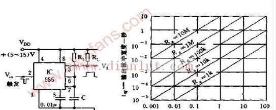
1 pin: External power supply negative terminal VSS or ground, under normal ground. Fiber Optic Rotary Joint, also known as optical fiber slip ring, optical fiber rotary joint, optical hinge, etc., is used to solve the problem of optical signal transmission between opposite rotating components, that is, to ensure that the transmission of optical signals is not interrupted due to rotation. fiber optic rotary joint,fiber optic slip ring,optical rotary joint Dongguan Oubaibo Technology Co., Ltd. , https://www.sliproubo.com
Pin 8: External power supply VCC, the range of the bipolar time base circuit VCC is 4.5 ~ 16V, and the range of the CMOS type time base circuit VCC is 3 ~ 18V. Generally use 5V.
3 feet: output Vo
2 feet: low trigger
6 feet: TH high trigger
4 feet: It is the direct clearing end. When the termination is low, the time base circuit does not work. At this time, regardless of the level of TH, the time base circuit output is “0â€, and the terminal should be connected to the high level when not in use.
5 feet: VC is the control voltage terminal. If the external voltage is connected to this terminal, the reference voltage of the two internal comparators can be changed. When the terminal is not used, the terminal should be connected to a 0.01μF capacitor to ground to prevent interference.
7 feet: discharge end. This terminal is connected to the collector of the discharge tube and is used as a discharge of the capacitor when the timer is used.