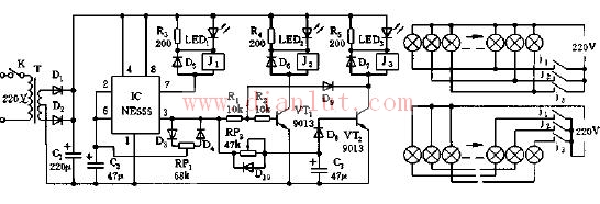
As shown in the figure, the rock lantern control circuit. The controller is composed of a step-down rectifier circuit, a 555 multi-vibrator, a lantern control circuit and the like. For a multivibrator composed of 555 and D3, D4, W1, C2, etc., adjusting W1 can change the charging and discharging time constant of the circuit, so that the duty ratio of the alternating square wave is 2:1. When the IC (555) 3 pin outputs a low level, the discharge of the corresponding internal discharge tube causes the 7 pin to be at a low level, illuminates the LED 1 lamp, the relay J2 pulls in, and the first group of lights is illuminated by the control; when the 3 pin outputs When the level is high, BG1 is turned on, the LED2 light is turned on, the relay J2 is closed, and the second group of lights is turned on by the control; meanwhile, the first group of lights is off because the relay J1 is released. At this time, the capacitor C3 is charged. When the voltage on C3 is charged to 1.3V, BG2 is turned on, J3 is turned on, and LED3 is turned on, and the third group of lights is turned on accordingly. In addition, due to the saturation conduction of BG2 and the clamping action of D9, BG1 is turned off, relay J2 is released, and the second group of lights is off. In this way, by adjusting W1 and W2, the three sets of lanterns are turned on and off for a while, as the lanterns roll, and Zhou Yu resumes. Transformer B uses 5VA and secondary 2×12. Twisted-pair, Cable to optical fiber, waveguide and other transmission media are conductive media, and electromagnetic wave in free space in the long distance propagation is non-conductive media transmission; Attenuation is therefore a complex function of distance and is influenced by the atmosphere around the Earth. The main factors affecting propagation attenuation are: propagation frequency band F, propagation distance L and electromagnetic wave rate C(close to the speed of light). Free space propagation loss of microwave segment signals such as satellites is about 36000 km from the ground. The beam diverges with distance. High-power klystrons can transmit signals up to kilowatts, while satellite transponders can only be powered by solar energy. The satellite's limited surface area makes it difficult to transmit hundreds of watts of downlink power. As a result, the ground station's received signal power is only microwatt level and includes a compensation effect of tens of decibels of the gain of the receiving and transmitting antennas. 2.4G or 5.8G Antenna Signal Booster ,2.4G Outdoor Antenna ,2.4G indoor Antenna ,2.4G Antenna Yetnorson Antenna Co., Ltd. , https://www.xhlantenna.com