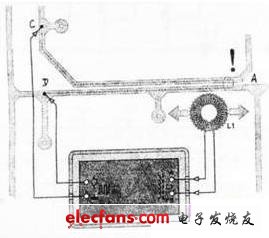
In the process of making the printed board, after the printing and etching process is completed, some problems will be encountered. For example, the place where the copper berth should not be connected is connected (bridge), that is, a short circuit fault occurs. Here is a printed circuit board short-circuit detector circuit that can be used to detect the above-mentioned faults of the printed board. First, the working principle If a short circuit occurs in a place where a part of the printed circuit board is not connected, it is only necessary to have a signal current in the part j, so that a magnetic field is generated in the local area. The magnetic field can be detected by the short-circuit detector described here. When detecting, the detector will sound at the same time as the short-circuit sounds and the LED flashes to show the position of the short circuit. The detector circuit is shown below. For example, when there is a short circuit at the A of the printed board, see the right figure, it is only necessary to use a set of pulse signals at two points C and D, and then use the coil (which can be self-made) to pick up the signal of the magnetic field. In order to improve the detection sensitivity, the signal frequency is selected to be 39 kHz (ultrasonic frequency). The signal picked up by the coil L1 is amplified by the operational amplifiers IC1a to IC1C (TS9241N), and then divided by the SC3 (74HC4O4O) after being shaped by the Schmitt trigger circuit IC2 (74H132). The potentiometer P1 in the circuit is used to adjust the cover of the operational amplifier IC1. The socket J1 in the circuit can be shorted to some two points according to the user's needs to select the frequency division signal. This signal is then output to an alarm circuit composed of IC2C, IC2D and buzzer to make a sound. At the same time, the frequency-divided signal outputted by the (11) pin of the frequency divider IC3 drives the LED (D2) to emit light through the resistor R16 to indicate an alarm. (11) The frequency division signal of the foot is 29 kHz / 212 = 7 Hz. When the LED is illuminated, it may be flickering light or continuous light, depending on the state of the foot (11) when the crossover counter IC3 is stopped. The circuit shown below is powered by battery. In order to display the normal power supply of the power supply, IC2B plus Rl3 and CIO are used to form a 2Hz multivibrator, which is displayed by LED (D1). Rl4 is a current limiting resistor to ensure that D1 is in a micro power state. The current through the LED is approximately 1 mA. The signal source required for the detection coil L1 of the detector is completed by IC1's fourth operational amplifier IC1D. IC1D, R17, R18, R19, potentiometers P3 and C11 form a multivibrator, which generates the detection signal. Its frequency is determined by the equation f0=2.26.7kHz~39kHz, which can be adjusted by p3. C11 and R19 can also be changed to change the frequency of the multivibrator. It can be seen from the above that since the signal frequency is a little bit frequency, this limits the occurrence of other harmonics of the current of the detection signal source. Inductor L2 in the signal source is a low pass filter that is in series with the output. C12 is a DC-blocking capacitor connected in series with inductor L2 through resistor R2O to prevent DC current from passing through the inductor. The operational amplifier IC1 is model TS9241N with an operating voltage of 2.7~+12(v) and an output current of up to 80mA. The high output current of IC1 makes the final output of amplifier IC1, no need to add amplification, in fact, IC1 requires only 20mA. As mentioned above, the circuit is powered by a battery, and its value is +3V. Two AA batteries can meet the circuit requirements. As can be seen from the power supply circuit in the lower left corner of the figure below, since half of the power supply voltage (1.5V) is a virtual location, there are two grounding points when the board is fabricated. When using the battery specifically, the tapping method is adopted for the two batteries to achieve the purpose of connecting the virtual ground. Wuxi Ark Technology Electronic Co.,Ltd. , https://www.arkledcn.com