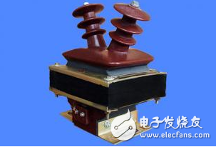
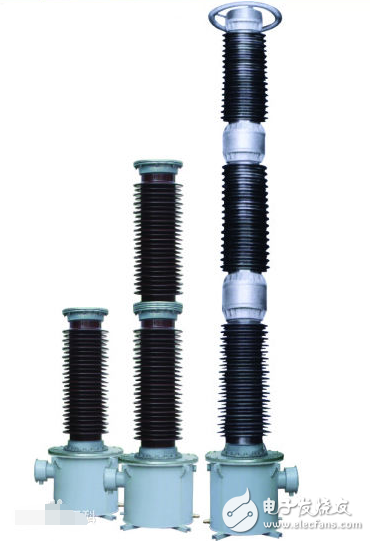
A voltage transformer (PT, Voltage Transform, or VT for short) is similar to a transformer and is an instrument used to change the voltage on a line. However, the purpose of transforming the voltage of the transformer is to deliver electrical energy, so the capacity is very large, generally in kilovolt-amperes or megavolt-amperes; the purpose of the voltage transformer to convert the voltage is mainly for measuring instruments and relays. The protection device is used to measure the voltage, power and power of the line, or to protect valuable equipment, motors and transformers in the line when the line fails. Therefore, the capacity of the voltage transformer is very small, generally only a few volt-amperes. Dozens of volt-amperes, no more than one thousand volt-amperes. The entry introduces its basic structure, working principle, main types, wiring methods, precautions, anomalies and processing, and ferromagnetic resonance. The basic structure of a voltage transformer is very similar to that of a transformer. It also has two windings, one called primary winding and one called secondary winding. Both windings are mounted or wound around the core. There is insulation between the two windings and between the windings and the core, so that there is electrical isolation between the two windings and between the windings and the core. When the voltage transformer is running, the primary winding N1 is connected to the line, and the secondary winding N2 is connected to the meter or the relay. Therefore, when measuring the voltage on the high-voltage line, although the primary voltage is high, the secondary is low-voltage, which ensures the safety of the operator and the instrument. At present, smart grid technology has developed rapidly, and it has become a major research topic in global energy development and transformation. Among them, various types of electrical signal measurement technology and its sensors are the basis for realizing smart grid monitoring, control, analysis and decision-making, as well as smart grid. The key to development. The accuracy, reliability, convenience and rapidity of voltage transformers are the key technical requirements in energy metering and relay protection, power system monitoring and diagnosis, and power system fault analysis. The electromagnetic voltage transformer (PotenTIal Transformer, PT) and the Capacitor Voltage Transformer (CVT) are widely used in power systems. Although the capacitive voltage transformers and electromagnetic current transformers commonly used in power grids are mature and have long-term operation and maintenance experience, their measurement linearity is poor, transient response speed is slow, and electromagnetic current mutual inductance The transient error characteristics of the device are also not ideal. Traditional electromagnetic voltage transformers have the characteristics of large weight and large volume, and with the development of ultra-high voltage power grids, the insulation strength requirements are more and more difficult. At the same time, due to the iron core, ferromagnetic resonance overvoltage and The shortcomings such as the dynamic range brought about by ferromagnetic saturation have become less and less suitable for the development trend of the current intelligent power grid. Compared with electromagnetic voltage transformers, capacitive voltage transformers have more advantages, and their voltage divider structure can improve the dynamic range of the transformer, making it easier to improve the insulation strength. However, the transformer cannot track the voltage change in time, and cannot meet the requirements in the relay protection system. Moreover, the transformer can capture the high-frequency overvoltage waveform, and cannot meet the power system fault diagnosis and online monitoring requirements, and the capacitive voltage. The RLC circuit composed of internal energy storage components such as coupling capacitors, compensating reactors and intermediate transformers in the transformer will make the transient characteristics of the capacitive transformer worse, so that when a system such as a voltage drop occurs, the capacitive voltage mutual inductance The output of the device does not immediately follow the change of the primary input, and under high frequency overvoltage, the secondary side output may have high frequency oscillation caused by ferromagnetic resonance, which cannot reflect the primary side input waveform. The use of electromagnetic voltage transformers and capacitive voltage transformers is also limited in applications where direct measurement is not readily possible, such as high voltage bushings, transformer winding joints wrapped by insulation. Ultra Transparency High Resolution Sky Curtain Ultra Transparency High Resolution Sky Curtain,Led Ad Wall Display Screen,Outdoor Led Digital Signage,Application Of Display Grille Screen Kindwin Technology (H.K.) Limited , https://www.ktlleds.com

Analysis of wiring application of voltage transformer
What is a voltage transformer?