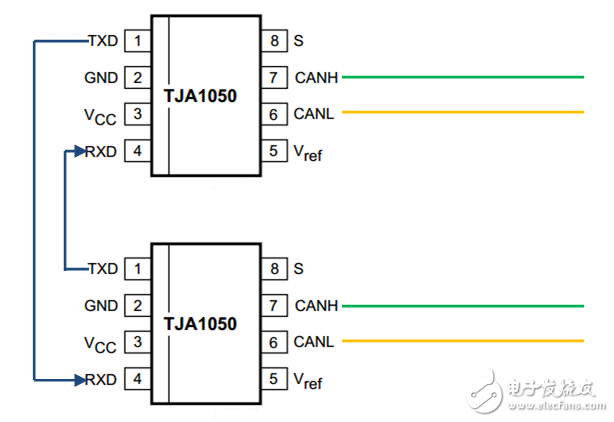
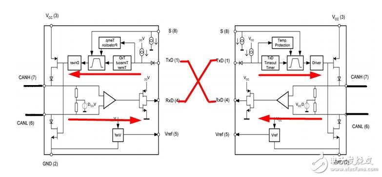
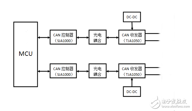
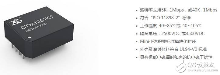
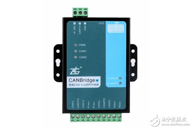
CAN repeaters are commonly used in large CAN networks. They extend the transmission distance, change the topology and isolate interference, but also increase the design cost. Some people say that as long as two CAN transceiver chips can implement CAN relay function. Can't you do it? Let's give a brief analysis to everyone. First, CAN transceiver introduction ISO 11898 is an international standard for high-speed communication in automobiles using the CAN bus protocol. The CAN transceiver is the interface part of the data link layer and the physical layer in the protocol. Common CAN transceiver chips are NXP (formerly Philips) PCA82C250/251, TJA1050/1051 and other models. Since the overall pin and function of the PCA82C250 and TJA1050 are compatible, we will take the TJA1050 as an example. Second, the analysis of the error scheme of two CAN transceiver chips First, a brief introduction to the TJA1050. As shown in the figure below, the TJA1050 has a total of 8 pins, TXD is the transmit data, RXD receives the data, VCC is connected to the 5V voltage, and GND is grounded. CANH and CANL are two differential outputs of CAN. 8 feet are selected for CAN bus mode, and 5 feet are reference ground. RXD and TXD must be very familiar to everyone. In the RS-232 protocol, as long as the RS-232 TXD and RXD of the two devices are cross-connected and GND is common, the two devices can communicate. So some people thought that if the TXD and RXD of the two TJA1050 chips are also cross-connected, can the relay function be realized? The circuit in the figure below seems to work, but in reality this circuit is not available. If this circuit is connected to the CAN bus, when the dominant level enters from TJA1050(A), RXD=0 of TJA1050(A), and TXD=0 of TJA1050(B), CAN output of TJA1050(B) Sex level. Due to the self-feedback of the chip, TJA1050(B) will read the dominant level and RXD=0, while TJA1050(A) has TXD=0, which continues. Since the TJA1050 has the explicit protection function of the TXD pin (the PAC8250 does not have this function), the CAN transceiver will be disabled when the maximum allowable TXD dominant time is exceeded. Third, the correct design of the CAN repeater The following figure shows the hardware block diagram of the CAN repeater, which is mainly composed of MCU, CAN controller and CAN transceiver. The MCU is responsible for buffering and forwarding data. The CAN controller converts the data into a CAN frame format and finally accesses the CAN network through the CAN transceiver. Most MCUs have integrated CAN controllers on-chip, such as NXP's LPC2119. The CAN controller and the CAN transceiver are isolated by optocoupler, and the CAN transceiver driver uses an isolated DC-DC module. In this way, not only the electrical isolation between the two CAN interfaces but also the isolation of the repeater and the bus is realized. Although this adds to the complexity and cost of the repeater hardware to a certain extent, it is worthwhile. Or you can use ZLG Zhiyuan Electronics CTM1051KT as the representative of the isolated CAN transceiver, including isolated DC-DC, signal isolation circuit, CAN bus transceiver circuit, basic bus protection. Compared to traditional designs, the CTM series offers higher integration, higher reliability and competitive pricing, helping users reduce overall design risk and procurement costs. Fourth, intelligent CAN bridge repeater ZLG Zhiyuan Electronic CAN Isolated Bridge Repeater Hub Series, with 2 or 4 electrically isolated CAN bus interfaces, can realize the relay function of CAN-bus network, and can store and store data between CAN networks of different speeds. . The main applications are as follows: (1) The use of this series of products can increase the load node and extend the communication distance, and realize the function of network relay expansion; (2) The communication baud rate of each channel can be arbitrarily configured independently to realize CAN network interconnection with different communication baud rates; (3) This series of products has powerful ID filtering conversion and data conversion functions, and the accurate acceptance ID configuration minimizes the load on the CAN bus. Or change specific IDs and data to achieve the goal of removing interference data and distinguishing between different devices; (4) It has strong anti-interference ability. When the user's equipment CAN is subjected to strong interference, it may cause crash or damage. After connecting this series of products, it can isolate the normal operation of the interference protection equipment. Thermal Printer ,Thermal Label Printer,Thermal Receipt Printer,Bluetooth Thermal Printer ShengXiaoBang(GZ) Material Union Technology Co.Ltd , https://www.sxbgz.com