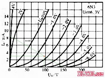
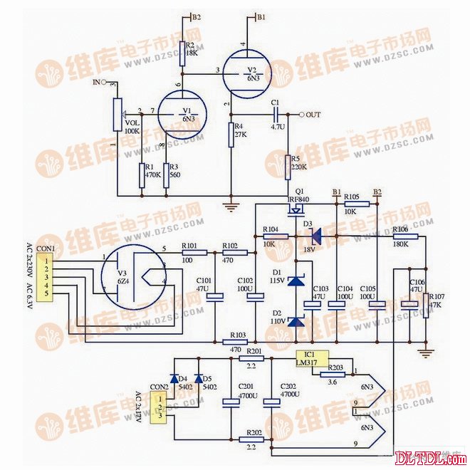
The following is a preamplifier circuit with a two-stage circuit directly coupled. The first stage is voltage amplification and the second stage is cathode buffer output. It can be said that it is a simple and easy to do circuit, but it should be noted that the signal output from this circuit is reversed, and the line output from the rear stage circuit to the speaker should be adjusted. 6N3 bile preamplifier because of which one of the Tianyi AD-8* parallel pure class A power amplifier sound poor sound, even less than the homemade LM4766 set successfully put ready to disintegrate, changed to pure post-level. For a time, you can't match the materials you need, and use the free time to make a tube front with it. First, the choice of circuit: This time I hope to use the existing parts on hand and the lower cost to make, the famous machine circuit is definitely not in line with the requirements, because the tubes used in these famous machine circuits are being smashed into high prices, and hundreds or more of them will be moved. Not what my generation can afford. The 6N3 was originally designed for TV broadcast VHF/UHF amplified dual triodes. This is a very good tube. The sound is between 6N11 and 12AX7. It is both musical and acoustic. The most important thing is that the price is very low. The import price of the same tube 5670 is only 8 yuan, which is very good value. The low price does not mean that it is rubbish. The high price does not mean that the tone is top, one is that the thing is more expensive, and the other is the hype of the merchant. The main reason why 6N3 and similar tubes have not been hyped up so far is that they are not universal in pin arrangement and the output of 6N3 and its similar tubes is too large. The 6N3 characteristic curve is shown in Figure 1. It can be seen from the 6N3 characteristic curve that this is not a large dynamic tube. The screen supply voltage should not exceed 150V, and the maximum gate negative voltage does not exceed -4V. Curves above -4V will bend clearly. The working point should be selected between -1.5V and 2.0V, and the input voltage should preferably not exceed 0.7V. The whole machine circuit is shown in Figure 2. V1 uses 1/2 6N3 for common cathode amplification, and V1 anode load resistance takes less value to 18K to obtain a larger range of anode current variation, while less distortion, calculated magnification. It is about 14.5 times. V2 uses 1/2 6N3 as the cathode output, which makes the circuit drive a constant voltage gain for different complex loads. Direct coupling between V1 and V2 makes the frequency response of the whole machine wider, which reduces the adverse effects caused by the coupling capacitor. The amplifying circuit is very simple, and there are only a few resistor and capacitor parts. The purpose is to simplify the circuit and reduce the manufacturing cost. The amplifier circuit is relatively simple and attaches great importance to the power supply. The high voltage of the power supply section is rectified by the rectifier diode and filtered by the bidirectional π-type filter circuit composed of C101, C102, R102, and R103 before being sent to the voltage regulator composed of Q1 and the like. The circuit is regulated. The advantage of using a bidirectional π-shaped filter circuit is to reduce the power ripple and also filter out all interference from the power supply grid to make the sound more pure. The regulated power supply uses the FET as the power supply regulating tube. The FET is different from the triode in that it is a voltage-controlled device. It has similar transmission characteristics as the electron tube. It only needs to drive the voltage without driving current. The FET is used as the power supply for the power supply regulating tube. High speed, low internal Yin, good sound quality and so on. The filament power supply is supplied by a constant current source composed of LM317. The constant current source is characterized by good sound quality, but the adjustment trouble is only suitable for amateur production. Domestic bile 6N3 preamplifier circuit Second, the circuit board design: Most of the enthusiasts used scaffolds when making the amplifiers. Because many years ago, there were amp fever enthusiasts who wrote that the scaffolding was more buzzing than the circuit board wiring. In fact, this is a misunderstanding. Whether the buzz is that the scaffolding will not shed, the circuit board routers do not understand the wiring, whether the buzz is in the level of technology, not in the way of manufacturing. This is like learning kung fu. It is not about learning Shaolin or Wudang, but about the level of skill. In today's computer technology, circuit board wiring is much more convenient and faster than scaffolding. Figure 3 is the circuit board layout diagram of the machine. The following are some points of the circuit board layout design of the machine. 1. Consider globally on the layout, the signal transmission is from right to left, and the power supply part is on the left side. This layout can avoid the mutual interference between the large and small signals, the interference of the power supply circuit and the power transformer to the amplification circuit. 2. The left and right channels are symmetrically placed up and down, the power supply is in the middle inner ring wiring, and all signal lines and signal transmission lines are routed on the upper and lower sides. The inner loop of the electromagnetic field generated by the power trace does not interfere with all audio signals on the outer loops on the upper and lower sides. 3. All power supply circuits must be routed in parallel in the same current loop. All the traces of the same current loop must also be connected in parallel, so that the electromagnetic fields generated by the power trace and the signal loop will never overlap. At the intersection, the electromagnetic field generated by the power trace does not interfere with the audio signals on all signal traces, and the electromagnetic fields generated between the signal loops do not interfere with each other. 4. Use the widest possible copper film trace, the weak signal is far away from the strong signal, the large signal trace is far away from the small signal trace, and the signal strength and the disparity trace are never allowed to parallel the long distance. 5. In a place where there is no wiring, a large area of ​​copper is connected to the power supply ground, and the same casing acts as a double screen to improve the anti-interference ability. 6. Try to use more jumpers to make the traces the shortest and most direct, so as not to wrap around the wires, so that the electromagnetic fields generated by the current loops overlap each other and affect the sound quality. 7. All the traces are arranged according to the current loop to arrange how to route. There is no star grounding advocated by the masters. Although the star grounding has a good signal-to-noise ratio, it is not the best wiring method. The loop analyzes how to route, the mutual interference between the current loops is the smallest, the signal transmission path is the shortest, the signal-to-noise ratio is the highest, and the sound quality is the best. Third, the selection of materials: After the PCB board is designed, use the laser machine to transfer the smooth surface of the thermal transfer paper (adhesive paper backing paper), then transfer it to the copper-clad board with a photo laminator, and etch the rosin after drilling all the holes. Alcohol water can be used to mount welding elements. The input and output sockets use the most affordable RCA socket, and the volume potentiometer has a great influence on the sound quality. The ALPS 27 blue molded case potentiometer is used. The two screen load resistors and cathode load resistors of R2 and R4 are British resistors, which are used to mitigate the phenomenon that the high frequency tube such as 6N3 is slightly rushed in the sound. The remaining resistors use DALE resistors. Both the filter capacitor and the decoupling capacitor are selected from the Philips Hexagon Electrolysis. The Philips Capacitor is characterized by its ease, stretch, smoothness, extravagance and low price. The rectifier tube is made of domestically produced*, and the sound is rougher and weaker than the imported pipe, but the price is low. 6N3 and its similar authors have three kinds of hands: domestic 6N3, Russia 6H3, US GE 5670, domestic 6N3, regardless of high frequency or low frequency, severely shrink, no dynamic, narrow sound field, Russia 6H3 high and low frequency comprehensive, extended Good, sound, cold, medium frequency is slightly weak, the United States GE's 5670 high and low frequency is also fully extended, dynamic, sound transparent, medium frequency is slightly fuller than 6H3, used for the best 5670. Those who are qualified can use the WE396 of Xidian, whose sound is unmatched by the above three tubes, but the price is too expensive and difficult to find. The output coupling capacitor uses Sibi 4uF 200V white film capacitor, the sound is comprehensive and the price is very low, only 3 yuan. The power transformer uses the power transformer of the five-lamp tube radio produced in the 1950s and 1960s. The 6N3 filament power supply transformer uses the power transformer that was removed from the black-and-white TV. These ancient transformers are made seriously and the materials are more abundant than the domestic transformers that are now cutting corners. The disadvantage is that the silicon steel sheet used has a large iron loss and the sound is not full and full. The casing is modified with the old CD casing, and the front panel is replaced with a solid wood panel to facilitate the opening, and the rear panel is replaced with a thin aluminum panel. The machine uses a thin aluminum plate to separate the power transformer from the circuit board to prevent the power transformer from leaking magnetic interference to the amplifier circuit. The two transformers are also separated by aluminum plates to avoid mutual interference between the transformers. The volume potentiometer is connected to the front panel through a transparent hose and a long aluminum shaft to control the volume, and then sealed with a heat shrinkable tube. Fourth, the indicator test: Subject to the conditions, all test results are derived from the YDS996A function signal generator and the CA8120 dual-track oscilloscope. The test tube used is the domestic 6N3. The measured magnification of this machine is about 12 times, which is quite close to the theoretical calculation. The frequency response characteristic can achieve high frequency response up to 1MHZ in small signal output, high frequency response in large signal output is about 150KHZ, and the maximum undistorted output voltage is about 14V. Tested by square wave, triangle wave and sine wave, no small oscillation or large signal output has no oscillation, no overshoot and no distortion. Starting from 10KHZ, as the frequency increases, the right angle of the square wave begins to slowly round until the 1MHZ square wave becomes a sine wave. Connect this unit to the Tianyi AD-66H combined power amplifier, open the AD-66H volume potentiometer to the maximum, and close the speaker tweeter with the ear, only increase the original noise floor of the AD-66H. Very slight rustling thermal noise, which is even better than many transistor machines. Fifth, listening to the price *: The sound of this machine is neither warm and warm, nor is it glamorous and beautiful. Its voice is not warm, not ruthless, and it is delicate, elegant, smooth and soft. The high and low frequency extensions are quite excellent. The low frequency is not a hot type, but it is more introverted and ups and downs. When playing the first "Tianquan" of TIS's "Dianman Dreamwalking", the bass drum is deep and flexible, and the bass stick The ground is immersed in a dip, and the internal organs are trembled with a submerged bass. The high-frequency is fine and smooth, and it can smooth the high-frequency rounding from the CD machine with a slight burr, and the sound of the triangle rank is smooth and transparent. The detail reproduction is better, and more detail can be heard compared to some other pre-biliary stages. The IF is not full. Compared to other biliary MFs, it is slightly lighter. It is similar to the IF's mid-range style. It is a soothing and soft mid-range. This machine has a strong personality. Regardless of the sound source of any tone, its distribution of high, medium and low tri-band energy is roughly equal, and the tone is roughly equivalent. It can filter out the rough sound from the sound source. Education, relaxation and pleasure. Such a simple circuit, such a low-cost production, what is the answer? EQM(ECM)
EQM series motors are designed with advanced electronic control technology, make the motor efficiency greatly increased,the external structure design of EQM series motors will maintain the similar external structure design as YZF series motors,motor accessories such as fan blades, rings or grids.brackets for EQM motors are the same as YZF series`. therefore EQM series motors can completely replace the YZF series motors without any other changes.Comparing with YZF series motors, EQM motors display an obvious advantage in energy saving. saving up to 70%.It can greatly reduce the electricity cost for motor operation and carbon dioxide emissions Not only that.due to the heating of EQM series motors themselves are very low.it would lead to the entire
refrigeration system works more efficient and make motor running more stable and reliable
Centrifugal Fan,Centrifugal Blower,Centrifugal Blower Fan,Centrifugal Air Blower Hangzhou Jinjiu Electric Appliance Co Ltd. , https://www.jinjiufanmotor.com