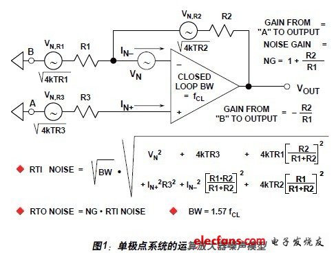
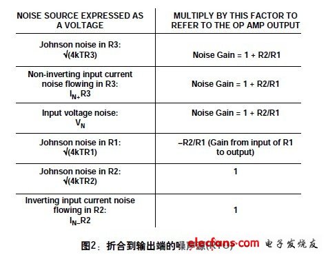
We have already pointed out that any noise source that is one-third to one-fifth less noisy than some larger noise sources can be ignored with almost no errors. At this point, the two noise voltages must be measured at the same point in the circuit. To analyze the noise performance of an op amp circuit, it is necessary to evaluate the noise contribution of each part of the circuit and determine which noise is dominant. To simplify subsequent calculations, the noise spectral density can be used instead of the actual voltage so that the bandwidth does not appear in the calculation formula (the noise spectral density is generally expressed in nV/Hz, which is equivalent to the noise in the 1 Hz bandwidth). If you consider the circuit in Figure 1 - an amplifier consisting of an op amp and three resistors (R3 represents the source impedance at node A), six independent noise sources can be found: Johnson noise of the three resistors, op amp voltage Noise and current noise at each input of the op amp. Each noise source contributes a certain amount of noise at the output of the amplifier. The noise is usually specified by the RTI, or converted to the input, but it is often easier to calculate the noise converted to the output (RTO), which is then divided by the noise gain (non-signal gain) of the amplifier to obtain the RTI noise. Figure 2 below details how the various noise sources in Figure 1 are reflected to the op amp output. The current noise effects on the inverting input need further discussion. This current IN– does not flow into R1 as expected – the negative feedback around the amplifier keeps the potential at the inverting input constant, so the current flowing from this pin can only flow into R2 with negative feedback, resulting in an IN – R2 output voltage. It is also possible to consider the voltage generated by the IN-inflow parallel combination of R1 and R2, and then amplify by the noise gain of the amplifier, but the result is the same, and the calculation is more complicated. Note that the Johnson noise voltage associated with the three resistors is included in the expression in Figure 2. The Johnson noise of all resistors is (4kTBR), where k is the Boltzmann constant (1.38 & TImes; 10–23 J/K), T is the absolute temperature, B is the bandwidth (in Hz), and R is the resistance (in ). A simple relationship that is easy to remember is that the 1000 resistor produces a Johnson noise of 4 nV/Hz at 25oC. The above analysis assumes a single-pole system where the feedback network is purely resistive and the noise gain versus frequency curve is flat. This applies to most applications, but if the feedback network contains reactive components (usually capacitors), the noise gain is not constant over the target bandwidth and more complex techniques must be used to calculate the total noise. Desktop Dry Herb Vaporizers,Environmentally Friendly Dry Herb Vaporiser,Professional Production Of Hay Evaporator,Small Electronic Hay Vaporiser END GAME LABS , https://www.eglvape.com
