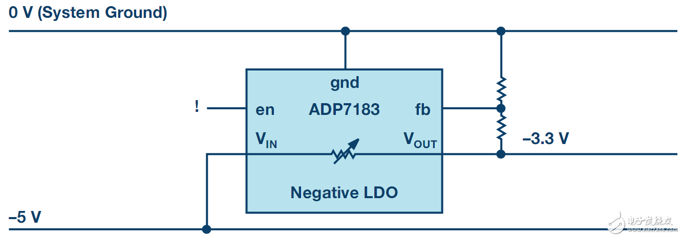
When measuring negative voltage system signals, the signal is not stable? Negative voltage linear regulator helps you hold "negative energy"! ! When it comes to voltage, everything is relative. There are different potentials between different electrical conductors. This means that one voltage can be higher than the other. In this case, the description of "negative voltage" is generally not used. The negative voltage we mean is a voltage lower than the ground potential of the system. Figure 1 is an example of a 3.3V supply voltage and a 0V system ground potential. In this system, the sensor's signal needs to be measured and recorded. These signals may be between +2.5V and –2.5V. Figure 1. Positive Linear Regulator Producing Negative Voltage To detect these signals, we used an op amp with a positive supply voltage of +3.3V and a negative supply voltage of –3.3V. A positive voltage of +3.3V is already available in the system. For the required –3.3V negative voltage, it can be generated using the –5V of the system. This voltage rail may come from a transformer-based power supply, which is usually not precisely regulated. In order to accurately generate –3.3V, we need to use a linear regulator. There are many linear regulators available on the market for positive voltages. Is it possible to use such a positive linear regulator in applications that need to convert negative voltages? The adjustable resistor in Figure 1 represents the trim component of the linear regulator. For this linear regulator IC, the voltage relationship between the VIN, VOUT, and GND connectors is identical, as in a positive voltage application. However, there are several disadvantages to using a positive linear regulator in this environment - 1) This circuit will use a resistor divider to regulate the output voltage based on the –5V rail, rather than based on the 0V rail, system ground. This causes interference and noise on the –5V rail to be directly coupled to the resulting –3.3V rail. In addition, the regulation accuracy is also quite poor. This inaccuracy is also coupled to the output voltage generated by –3.3V when the –5V supply voltage accuracy is only ±10%; 2) The I/O pins of the linear regulator device (such as the enable pin) will be referenced to –5V. If you need to monitor the power-up sequence for different voltages, you may need level shifting. Figure 2 shows the same system, but uses a linear regulator designed for buck negative voltage. These ICs are called negative linear regulators. ADI's new ADP7183 negative linear regulator is designed for lowest noise, highest power supply rejection ratio (PSRR) . This makes the device ideal for filtering applications that are sensitive to power supply noise. Figure 2. Negative Linear Regulator Producing Negative Voltage If a negative linear regulator as shown in Figure 2 is used, the resulting –3.3V is regulated against a 0V ground voltage. This will result in very low noise and accurate output voltage. In addition, the I/O pins are referenced to a system ground of 0V, eliminating the need for level shifting. In this way, special negative linear regulators are especially important when converting negative voltages or filtering negative voltages. Negative linear regulators on the market usually have limited supply. New products such as the ADP7183 (300 mA) and ADP7185 (500 mA) offer you a wider range of products available. Servo Systems,Servo Drive System,Servo Positioning Systems,Cnc Machine Ac Servo Zhejiang Synmot Electrical Technology Co., Ltd , https://www.synmot-electrical.com