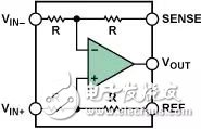
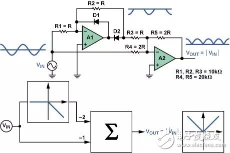
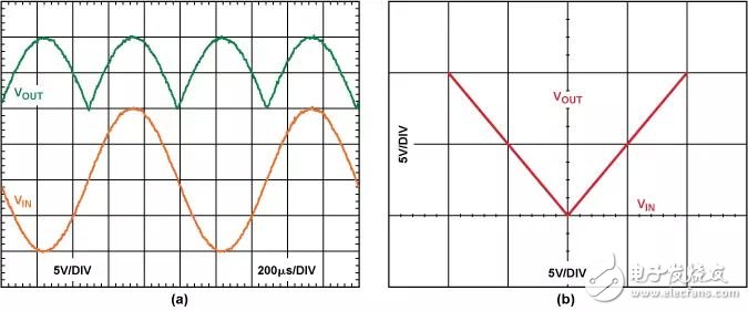
Traditionally, precision half-wave and full-wave rectifiers use carefully selected components, including high-speed operational amplifiers, fast diodes, and precision resistors. The large number of components makes this solution costly and does not get rid of the distortion of the components and the temperature drift. Today, we share an article by ADI Fellow Moshe Gerstenhaber, which describes a method— how to configure a two-channel differential amplifier—without any external components to provide a precise absolute output. This innovative solution can achieve higher precision, lower cost and power consumption than traditional solutions. As shown in Figure 1, the differential amplifier includes an operational amplifier and four resistors configured as a subtractor. Low-cost single-chip differential amplifiers with built-in laser wafer trimming resistors provide extremely high gain accuracy, low offset, low offset drift, high common-mode rejection, and better overall performance than discrete replacement devices. Figure 1. Differential Amplifier Traditional absolute value circuit Figure 2 shows a schematic diagram of a common full-wave rectifier circuit. This design relies on two fast op amps and five precision resistors for high performance. When the input signal is positive, the output of A1 is negative, so D1 is reverse biased. D2 is forward biased, thereby closing the feedback loop through R2 near A1 and forming an inverting amplifier. A2 adds the A1 output multiplied by the gain-2 and the input signal multiplied by the gain-1 to obtain a net gain of +1. When the input signal is negative, D1 is forward biased, thus closing the feedback loop near A1. D2 is reverse biased and therefore does not conduct. A2 inverts the input signal to produce a positive output. Thus, the output of A2 is a positive voltage, indicating the absolute value of the positive and negative inputs. Figure 2. Standard full-wave rectifier This design has several inherent performance and system disadvantages such as cost, crossover distortion, gain error, and noise. This design requires dual power supplies and many high-performance components to further increase cost and complexity. Since the input signal spans 0 V + ΔV and 0 V – ?V, the output of A1 must swing between –VBE and +VBE, so the response time may be longer. High-speed op amps and diodes can help alleviate this problem, but at the expense of higher power consumption. The gain accuracy of the absolute value output depends on the degree of matching of R1, R2, R3, R4 and R5. Even a small mismatch of a resistor can cause a large error between the positive and negative absolute peaks. The overall noise gain is 6, amplifying the op amp noise, offset and drift effects. Improved absolute value circuit Figure 3 shows a simpler, more efficient absolute circuit that requires only one AD82774 dual differential amplifier and one positive supply. When the input signal is positive, A1 acts as a voltage follower. The potential of the two inputs of A2 is the same as the input signal, so A2 only passes the positive signal to the output. When the input signal is negative, the A1 output is at 0 V, and A2 inverts the input signal. The absolute value of the input signal is finally obtained. Signals up to ±10 V can be rectified at frequencies up to 10 kHz. If the signal to be rectified is very weak, placing a pull-down resistor at the output of each op amp can improve circuit performance near 0 V. Figure 3. Single Supply Absolute Value Circuit Using the AD8277 This circuit seems simple, but functionally feasible, thanks to the excellent input and output characteristics of the AD8277 and single-supply operation. Unlike most single-supply applications, the input of the differential amplifier can be driven below 0 V. This allows the input of A1 to maintain a 0V output while accepting a negative input signal. The input is integrated with an ESD diode for more robust overvoltage protection. Figure 4 shows the input and output waveforms and characteristics of a 1 kHz 20 V pp input signal. Figure 4. (a) Input and output of a 1 kHz 20-V pp input signal (b) Input and output characteristics This improved absolute value circuit overcomes many of the shortcomings of conventional rectifier design and is of much value. The most prominent of these is the reduction in the number of components required: just one device. The external diode is removed and the crossover distortion is also eliminated. The laser wafer adjustment resistors are precisely matched to ensure a gain error of less than 0.02%. The circuit has a noise gain of only 2, with lower noise, offset, and drift. With a single 2 V to 36 V supply, the AD8277 has a quiescent current of less than 400 μA. in conclusion Precision full-wave rectifiers built with a single dual-channel differential amplifier go beyond traditional design in many ways. One of the most noteworthy is the elimination of high-performance external components and dual power supplies, resulting in a significant reduction in cost and complexity. The differential amplifier solution does not have crossover recovery problems and is optimized to achieve low drift over a wide temperature range. With the AD8277, a single IC can be used to achieve low power, low cost, high precision absolute value circuits. The AD8277 is a general purpose unity-gain difference amplifier designed for precision signal conditioning in applications requiring high performance and low power. The device not only provides excellent common-mode rejection ratio (86 dB) and high bandwidth, but also amplifies the signal beyond the supply rail. The on-chip resistors are laser trimmed for excellent gain accuracy and high common mode rejection ratio (CMRR). The gain of both devices is extremely low with temperature drift. With a common-mode range of almost twice the supply voltage, the AD8277 is ideal for single-supply applications that require a high common-mode voltage range. For more information on this device, please click "Read the original".
Wired headphones
Wired headphones have a plug-and-play setup. Simply plug it into your audio device and it can play your audio right away. With them, you don't run the risk of any unwelcome wireless interferences and pairing issues. Considering these factors, they're undeniably more user-friendly than wireless ones.
Wired Earphones,Best Neckband Under 1500,Best Earbuds Under 2000,Best Neckband Under 2000 Pogo Technology International Ltd , https://www.wisesir.net