led grow light bar, horticulture lighting, quantum board driver, 1200W LED Driver, 720W led grow light ShenZhen Fahold Electronic Limited , https://www.fahold.net
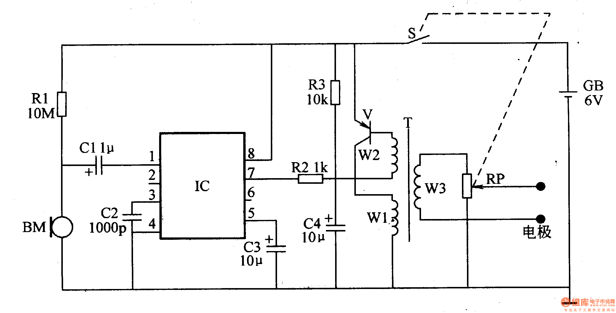
Circuit Operation Principle The electronic shooter circuit is mainly composed of a click detection control circuit and an electric pulse generation circuit, as shown in Figure 9-143. 
The click detection control circuit is composed of a microphone BM, an audio level detection integrated circuit IC (NJM2027D), and a peripheral RC element.
NJM2027D contains operational amplifiers, detectors, electronic switches, Schmitt triggers, output buffers and constant current sources. The functions of each pin are: 1 pin is the signal input; 2, 3 feet are gain control. 4; 4 feet for the ground; 5 feet for the recovery time control; 6, 7 for the level output; 8 for the power supply.
The electric pulse generating circuit is a self-excited multivibrator composed of a switching transistor V, a pulse transformer T, a potentiometer RP, a resistor R3, and a capacitor C4.
In the case of uninterrupted sound, the electronic snoring device does not work, and the two electrodes have no stimulation pulse output. When the user snoring, the microphone BM converts the sound signal into an electrical signal, and then joins the IC's pin through the capacitor C1, and after the circuit processing in the IC, the control level is output from the 7th pin of the lC, so that the electric pulse is generated. The circuit oscillates and generates a high-voltage pulse at both ends of the secondary winding W3 of the pulse transformer T. This high-voltage pulse (synchronized with the sound of the sound, if the sound stops, the high-voltage pulse disappears; if the sound is continuous, the high-voltage pulse is continuously output) Add the electrode to the user's hand or foot (not connect the electrode to the head or the heart, etc.) to change the sleeping position.
The RP is used to adjust the magnitude of the high voltage pulse.
By changing the capacitance of the capacitor C4, the pulse frequency can be adjusted.
Component selection
Rl-R3 uses 1/4W or l/8W carbon film resistors.
The RP uses a small synthetic carbon film potentiometer with a switch.
Cl, C3 and C4 are all selected from aluminum electrolytic capacitors with a withstand voltage of l6V; C2 uses ceramic dielectric capacitors.
V selects S8550 or C8550 silicon PNP transistor.
The BM uses an electret microphone (microphone) with a built-in FET.
T can be made of E7 core, the winding W1 is wound 30 åŒ with φO.l2mm enameled wire, W2 is wound 25 åŒ with φO.l2mm enameled wire, W3 is wrapped with φO.O9mm enameled wire around 600-800åŒ. An insulating layer should be applied between the winding W3 and the windings W1, W2.
The electrodes can be made of conductive rubber or phosphor bronze.