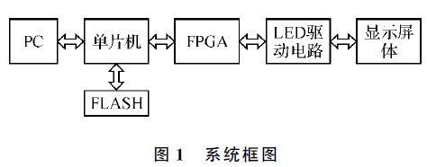
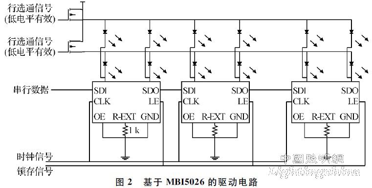
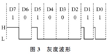
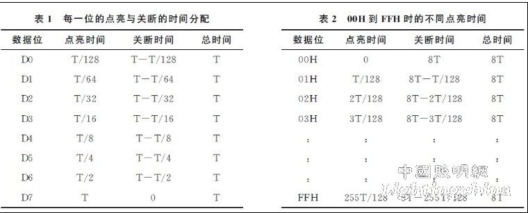
Introduction With the rapid development of the information industry, LED display as an important means of information dissemination has become a shining symbol of the modern information society. In recent years, LED display has been widely used in indoor and outdoor public places for service content and service purposes. Publicity, such as the release of information such as postal halls, telecommunications, sales offices, stations, airports, ports and stadiums, the release of government agencies' policies and decrees, the release and promotion of various market information, etc., including the opening ceremony of the Beijing Olympic Games. The "Gigantic Picture" also uses a huge LED display. With the implementation of the electronic industry standard "General Specifications for Display" and "LED Display Test Method", industry standards for various application areas, such as the Ministry of Public Security's "LED" Road Traffic Induced Variable Signs, Sports Industry Standards, "Sports Equipment Requirements and Test Methods Part 2: Display Screens" are also being actively developed. 1 system composition The LED display system block diagram is shown in Figure 1. The whole circuit uses the single-chip microcomputer as the control center to realize the control of the LED dot matrix data. The MCU first stores the data received from the PC into the FLASH, and then the MCU converts the data in the FLASH. Red, green, and blue data are stored in the RAM of the FPGA. The FPGA sends the data in its RAM to the 16-bit serial/parallel shift register and the 3/8 decoder. The 16-bit serial/parallel shift register (using constant current IC - MBI5026) and 3/8 decoder to transfer data to the dot matrix module. Finally, the dot matrix module will display the specific content. 2 LED drive circuit based on MBI5026 The LED display adopts a circuit structure driven by a row scan column, that is, a plurality of rows share a column drive, and a dynamic pattern is formed by a row to form a complete pattern. The driving circuit using MBI5026 is as shown in FIG. 2. The circuit shown is two lines of scanning, and more The structure of the row scan is similar. When the row strobe signal is low, the switch transistor (selecting the P-channel 4953) is turned on, the corresponding row is strobed, and the current flows from the power source through the LED to the constant current IC. LED illumination. The gray level adjustment of each LED is realized by serial signal. 3 bitwise time-sharing principle The so-called bitwise time-division lighting, that is, one bit of data is sequentially extracted from one byte of data, and the corresponding pixels are lit in 8 times, and each corresponding lighting time is different from the duty ratio of the off time. If the lighting time is increased from low to high, the combined lighting time will have 256 combinations. Define the lighting time plus the shutdown time as a time unit, set to T. Table 1 lists each Bit time lighting and off time allocation. [2] For example, to display grayscale data of 163 grayscale, decimal representation of decimal 163 is 10100011. Each bit corresponds to each lighting time and off time Empty as shown in Figure 3. If the defined data bit "1" is valid (lighted) and "0" is invalid (off), then Table 2 lists the different lighting times when the data is from 00H to FFH. As shown in Table 2, each time the data is incremented by one, The bright time is increased by T/128. According to the principle that the lighting time and the brightness are basically linear, the lighting time from 0 to 255T/128 corresponds to 256 levels of brightness. Of course, this brightness is a cumulative effect on time. The same data bit corresponding to all the pixels of the LED dot matrix screen is lit up once called a field, then 8 bits of data need to be displayed in 8 fields, which is called "8 field principle". In theory, 256 gray levels can be displayed in 8 fields. However, it can be seen from Table 2 that even if the data is FFH, it only lights up 255T/128 time in 8T time. The turn-off time can be close to 6T. The lighting time is only about 25% of the total time. Therefore, although the 8-field principle can achieve 256-level gray scale display, the brightness loss is too large. In order to improve the brightness, the "19 field principle", that is, 8-bit data points can be used. After 19 fields are displayed, D7 bit data is continuously displayed in 8 fields, and D6 bit is continuously displayed in 4 fields, which are successively decremented. Table 3 lists the lighting and turn-off times of each of the 19 fields. 


