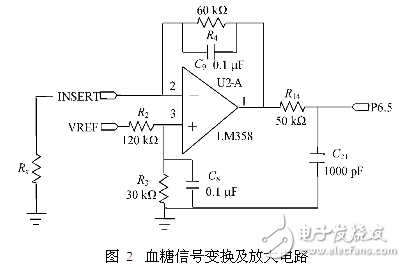
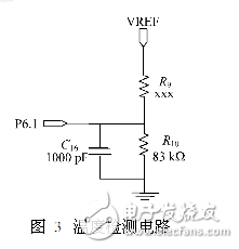
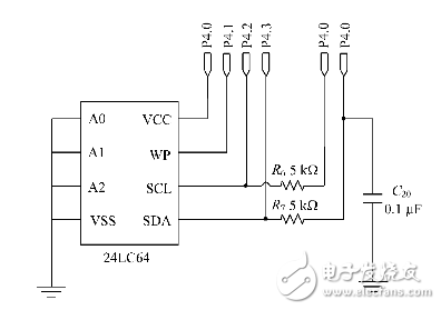
A design of a portable blood glucose meter is introduced. The design is mainly based on the low power consumption and accuracy, with the MSP430 series of single-chip microcomputer as the core, and the glucose oxidase electrode as the test sensor to test the blood glucose concentration faster. In addition, the designed blood glucose meter also has a storage function to help users view historical and changing trends in blood glucose levels. Blood glucose test circuit: After the blood is dropped on both ends of the enzyme electrode, free electrons are generated. Since there is an excitation voltage across the electrode, an directional current flows through the electrode. The excitation voltage is generated by the 1.5V regulation provided by the ADC module through resistor divider, which is about 300mV, which can generate directional current of μA level. Since the A/D conversion module measures the voltage, it is necessary to convert the directional current into a voltage and perform a certain amplification. The system uses the circuit shown in Figure 2 to achieve current to voltage conversion and amplification. The inverting end of the operational amplifier LM358 is connected to the enzyme electrode on the blood glucose test strip. When blood is instilled, the equivalent resistance Rx is between the electrode and the ground, and the current flowing through the resistor is proportional to the blood glucose concentration value in the blood. The MSP430's A/D module outputs 1.5V regulation through R2 and R3 to generate an excitation voltage of 300mV, which is applied to the ends of the electrode through the positive terminal of the op amp. R4 acts as a feedback amplifier that limits the output range of the op amp to the conversion range of the A/D module. When the PCB board is routed, since the trace between the op amp output and the ADC module input I/O port of the MSP430 is long, in order to ensure the accuracy of the measured value, the test voltage needs to be filtered, and C21 is used for filtering. To reduce the impact of external interference introduced by excessively long lines on blood glucose testing. The direct connection of the op amp to the capacitive load easily causes the output to oscillate. The role of R14 is to isolate the op amp and capacitor. Since there is a current flowing through the resistor R14, there is a voltage drop across the resistor, and the voltage signal is affected by this change. In order not to affect the accuracy of the blood glucose test, the value of R14 cannot be excessively large. Take 50Ω according to the experience value. Temperature detection circuit: Since the blood glucose test utilizes a bioelectrochemical reaction, an important factor affecting the reaction is temperature. Glucose oxidase activity is different at different temperatures. Even for blood of the same blood glucose concentration, the same excitation voltage is used, and the magnitude of the current generated by oxidation of glucose oxidase is different at different temperatures. Therefore, it is necessary to compensate according to the temperature to obtain the correct blood glucose concentration value. When the temperature is too high or too low, the glucose oxidase will completely lose its activity. At this time, the blood glucose meter needs to give an alarm, prompting the user that the meter can not operate at this temperature, and avoiding the wrong detection value. The temperature test circuit is shown in Figure 3. In the figure, R9 is the thermistor ET833, which has a negative temperature characteristic. R10 is a high precision resistor with a resistance of 83k Ω. The R9 is terminated by the 1.5V regulator output from the MSP430's A/D converter module. Since the 1.5V regulation is also the reference voltage of the A/D converter module, this connection can eliminate the A/D reference voltage jitter. The resulting conversion error. When the blood glucose meter works normally, the magnitude of the thermistor R9 is calculated by measuring the voltage of the P6.1 port, and then the temperature value is calculated according to the characteristic curve of the ET833 to perform temperature compensation. Data storage circuit: In order to facilitate the user to check the change of blood sugar at any time, the blood glucose meter has the function of storing blood sugar value. The user can not only query the historical value of each measurement, but also can query the change trend of the blood glucose level within the last 28 days, and formulate the correct medication mode according to the trend of blood sugar change to achieve the purpose of controlling the blood glucose concentration. The system can store up to 1000 historical data, each historical data needs 8B to save, the data contains two information of blood sugar concentration and test date, so 8000B storage space is needed. The 24LC64 is an E2 PROM chip produced by Microchip, which can store 8KB. Therefore, it is enough to select a 24LC64 chip. The specific wiring between E2 PROM and MCU is shown in the figure. P4.0~P4.3 are digital I/O ports of MSP430. P4.1 is a write-protected pin to avoid accidental writes to the EPROM due to external disturbances or program errors. P4.2 and P4.3 are the ports through which 24LC64 and MSP430 communicate. P4.0 is used to power the 24LC64. The purpose of powering the chip by using the I/O port is to reduce the overall power consumption during system operation. In addition, the electronic switch is saved, the cost is reduced, and the wiring is facilitated. Nintendo Switch Joy-Con,Nintendo Switch Console,Nintendo Switch Console Game,Nintendo Switch Joycons Shenzhen GEME electronics Co,.Ltd , https://www.gemesz.com