Many 0V to 30V or 60V adjustable DC output power supplies are available on the market, but there are few power supplies above 60V. This design example provides such a solution. Pharmaceuticals,2-Methyl- Propanoic Acid Monohydrate Price,2-Methyl- Propanoic Acid Monohydrate Free Sample,Pure 2-Methyl- Propanoic Acid Monohydrate Zhejiang Wild Wind Pharmaceutical Co., Ltd. , https://www.wild-windchem.com
There are now many fixed voltage switch mode power supplies (SMPS) that can be connected in series to achieve a higher fixed voltage. In order to obtain an adjustable output from an SMPS or a conventional transformer-based power supply, a linear regulator or a switch mode buck converter is required. For a buck converter, a MOSFET or an IGBT can be used as the switching element.
Typically, the high side switch uses a bootstrap IC or a pulse transformer. There are few optocouplers that drive MOSFETs on the market. Because they do not provide enough current to quickly charge the gate capacitance, these optocouplers are primarily used to drive low frequency MOSFET switches, such as solid state relays.
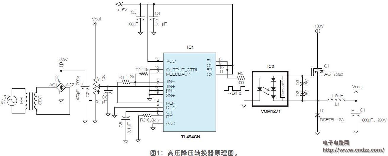
An attempt was made here to use a photocoupler (VOM1271) in a switching regulator with a built-in fast turn-off device. If a 200pF gate capacitor is connected to IC2, the switching times (ton and toff) are 53μs and 24μs, respectively. In view of this, the buck converter selects a switching frequency of 2 kHz. Texas Instruments (TI) TL494 (IC1) was selected as the pulse modulation controller.
Considering factors such as gate threshold voltage (VGS(th)), total gate charge (Qg), drain-source voltage (VDS), and drain current (ID), this example uses the AOT7S60 MOSFET as a switching element. Since VOM1271 can supply a voltage of about 8.4V, VGS(th) should be much lower than this value; Q1 has a VGS(th) of 3.9V, and when the voltage is 8.4V, good conduction performance can be achieved. IC2 is unable to supply more current (typically 45μA). To ensure switching speed and reduce switching losses, the gate charge should be kept low. The Qg of the MOSFET is 8.2nC.
After rectifying and filtering according to Figure 1, the buck line transformer is used to test the buck converter. The output voltage is continuously adjustable through the variable resistor R1 in the range of 5V to 70V. 
Figure 1: Schematic diagram of a high voltage buck converter 
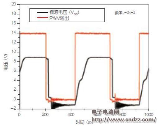
Figure 2: shows the gate-to-source voltage waveform and the IC1 output waveform at 70V output and 230Ω load.
It can be seen that although toff is fast enough, ton is still about 80 μs. For many switch applications, this turn-on process is slower. Setting the switching frequency to 2 kHz should not cause too much switching loss, especially for load conditions with large PWM duty cycles.
Although the value of L 1 is less than the calculated value of the input voltage range, the ripple can reach 80 mV to 120 mVP-P when the load is 80 Ω to 230 Ω. When the output voltage is 70V and the load is 230Ω, the ripple is 80mVP-P. Under the same working conditions, the voltage regulation rate is 0.75%. Although the efficiency varies with operating conditions, the measured efficiency is 92% at VOUT = 70V and IOUT = 0.3A. As the output current decreases, the efficiency also decreases.