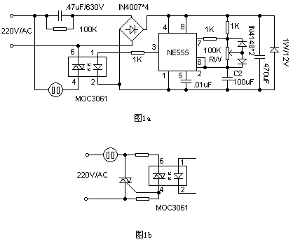
In the circuit, the NE555 is connected to a square wave generator with adjustable duty cycle. During the high-level output of the NE555, the zero-crossing-off type photocoupler (optocoupler is an electric-optical-electrical conversion device that transmits electrical signals by light. It consists of two parts: the light source and the light receiver. The light source and the light receiver are assembled in the same sealed casing, and are separated from each other by a transparent insulator. The pin of the light source is an input end, and the pin of the light receiver is an output end, and the common light source is a light emitting diode, and the light is received. The photodiode is also a photodiode. The photodiode is similar in structure to the semiconductor diode. The die is a PN junction with photosensitive characteristics and has unidirectional conductivity. Voltage. When there is no light, there is a small saturated reverse leakage current, that is, dark current. At this time, the photodiode is turned off. When exposed to light, the saturated reverse leakage current is greatly increased to form a photocurrent, which varies with the incident light intensity. And change), phototransistor, etc.) MOC3061 primary gets about 10mA forward working current, so that the internal gallium arsenide infrared emitting diode emits infrared light, will In the zero-crossing detector, the photosensitive bidirectional switch is turned on when the mains is zero-crossed, the electric motor of the electric fan is turned on, and the fan runs to supply air. During the low level output of pin 3 of NE555, the bidirectional switch is turned off and the fan stops. Pet(Polyester) Membrane Switch,Membrane Keypad Switch,Metal Dome Membrane Keypad Switch,New Design Membrane Keypad CIXI MEMBRANE SWITCH FACTORY , https://www.cnjunma.com
The circuit of Figure 2 is a typical power expansion circuit of MOC3061. When controlling a motor with high power, the power expansion circuit should be considered. When making, you can select the device by referring to the graphic parameters. Since the power supply adopts a capacitor voltage drop mode, the human body cannot directly touch the circuit board during the test.