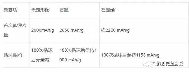
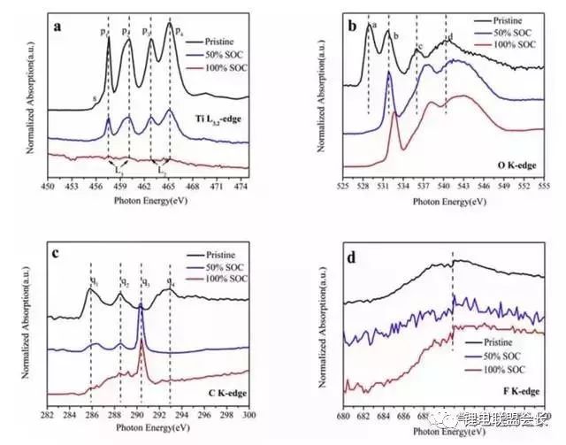
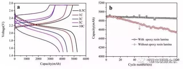
As a negative electrode material for lithium-ion batteries, nano-silicon carbon has high lithium storage capacity (its room temperature theoretical capacity is as high as 3580m∙Ah/g, far exceeding graphite (372m∙Ah/g)), good electronic channels, small strain and promote SEI film Stable growth environment. Based on the above advantages, the material is expected to replace graphite as the next generation high energy density lithium ion battery anode material. It is undeniable that there are also many problems on it: the volume expansion and contraction of silicon particles during the de-embedding process causes particle pulverization, shedding and electrochemical performance failure; solid electrolyte layer (SEI) on the surface of silicon particles The continuous growth of the electrolytic solution and the irreversible consumption of the physical source from the positive electrode. This article mainly introduces the research progress, preparation methods, applications and prospects of different structures of nano-silicon-carbon anode materials for lithium-ion batteries. Research progress of nano-silicon-carbon materials Early nano-silicon-carbon materials developed from the Lantern Festival structure to the walnut structure (as shown in Figure 1), and the density increased. Figure 1 Early walnut-like nano-silicon-carbon materials Subsequently, silicon-based materials developed in two directions, which are compatible with the current battery system with low capacity and meet the high capacity of electric vehicle systems. The main problem with low capacity (as shown in Figure 2) is the efficiency of the long cycle process and the compaction rebound. The former is related to the consumption of lithium and the growth of the SEI film, while the latter determines the actual volumetric energy density. The research and development process of low-capacity materials is different from the direction of high-capacity, which greatly increases the graphite content to relieve strain and reduce rebound. At the same time, the surface coating materials and corresponding heat treatment processes are carefully selected, and the liquid phase dispersion process with high safety is introduced. In terms of high capacity (Figure 3), the main problem lies in the subsequent cycle stability and efficiency problems caused by the volume expansion of silicon. In addition, due to its finer structure, compatibility with the current battery system and processing performance are relatively poor. . In order to solve the above problems, a low-cost, high-yield doped nano-silicon (D50 In addition, scientists have also developed a low-cost, green, pollution-free, flexible and controllable large-scale silicon-carbon composite preparation process. In the network, the conductivity of the material is improved: Figure 4 shows the morphology and electrochemical performance of the silicon-carbon composite with a capacity of 600mAh/g: Under the condition of an areal density of 2mAh/cm2, it exhibits excellent cycle stability and high Coulomb efficiency. Figure 4 Morphology (a) and electrochemical performance (b) of 600m∙Ah/g nano-silicon-carbon material Preparation method of silicon carbon anode material 1. Chemical Vapor Deposition When the chemical vapor deposition method prepares silicon/carbon composite materials, silicon element and silicon-containing compounds such as SiH4, nano silicon powder, SBA-15 and diatomaceous earth are used as the silicon source, and carbon or organic matter is the carbon source. Divided into the matrix, the other component is uniformly deposited on the surface of the matrix to obtain a composite material. The composite material prepared by this method has a tight connection between the two components of silicon and carbon, and has strong binding force. The active material is not easy to fall off during the charge and discharge process. It has excellent cycle stability and higher first-time coulombic efficiency, and the carbon layer is uniform and stable. Agglomeration occurs; for industrialization, the equipment is simple, the composite material has less impurities, and the reaction process is environmentally friendly. The most promising large-scale production is favored by scientists. 2. Sol-gel method The liquid composite method can well improve the dispersion problem of the material in the composite process. The silicon material in the silicon/carbon composite material prepared by the sol-gel method can achieve uniform dispersion, and the prepared composite material maintains a high reversible specific capacity , Cycle performance. However, carbon gel has poorer stability than other carbon materials. During the cycle, the carbon shell will crack and gradually expand, resulting in the breakdown of the negative electrode structure and reducing the performance; and the high oxygen content in the gel will generate more non-conductive materials. SiO leads to a decrease in the cycle performance of the negative electrode material, so the oxygen content is an important reference condition for determining which gel is used as the matrix. 3. High temperature pyrolysis method The high temperature pyrolysis method is currently the most commonly used method for preparing silicon/carbon composite materials. The process is simple and easy to operate. It only needs to place the raw materials in an inert atmosphere for high temperature cracking, and it is easy to repeat. During the pyrolysis process, the organic matter is cracked to obtain no Shaped carbon, the void structure of this carbon is generally more developed, which can better alleviate the volume change of silicon during charging and discharging. Tao et al. used SiCl as the raw material to obtain porous silicon by the thermal reduction method of metal magnesium, and then under an inert atmosphere, the organic carbon was coated by the high-temperature pyrolysis method to prepare a porous silicon/carbon composite material. It is excellent and can be directly used as a negative electrode material for lithium-ion batteries. The first discharge specific capacity reaches 1245mAh/g, and the specific capacity after 30 cycles reaches 1230mAh/g. 4. Mechanical ball milling The particle size of the composite material prepared by the mechanical ball milling method is small, and the components are uniformly distributed, and the silicon/carbon composite material prepared by the mechanical ball milling method has the advantages of simple process, low cost, high efficiency, and suitable for industrial production; because the method is two kinds The reaction materials are mixed under the action of mechanical force, so the agglomeration phenomenon of particles has not been effectively solved. Moreover, the combination of high temperature pyrolysis in most preparation processes is also the main reason that restricts the practical application of mechanical ball milling. 5. Hydrothermal synthesis method Generally, small-molecule organics are used as carbon sources, and after ultrasonically dispersing them with silicon powder in a solution, the silicon/carbon composites are prepared by hydrothermal reaction in a sealed autoclave, and then carbonized at high temperature. The hydrothermal synthesis method is easy to operate, has high product purity, good dispersibility, and easy control of particle size; however, this method has high energy consumption and low yield, and is not suitable for mass production. 6. Electrospinning Electrospinning technology refers to the process of polymer solution (or melt) forming fibers under the action of high-voltage electrostatic electric field, which can produce fibers with a diameter of tens to hundreds of nanometers and a large specific surface area. Lithium-ion batteries based on silicon-carbon materials with different structures 1. Coated composite material The advantage of the coated silicon/carbon composite material is its high silicon content, which helps to increase its lithium storage capacity. The well-coated carbon layer on the surface can effectively buffer the volume effect of silicon, enhance the electronic conductivity, and at the same time produce a stable SEI film to stabilize the interface between the composite material and the electrolyte. In the traditional core-shell structure of silicon-carbon composites, during the process of lithium insertion, the violent volumetric stress of silicon causes the surface carbon layer to crack, the composite structure collapses, and the cycle stability decreases rapidly. There are usually three solutions to improve its cycle stability. Properties: Improve the microstructure of the carbon layer, modify the silicon into a nanoporous structure and then coat the carbon layer to prepare nanofiber silicon/carbon composites. The cycle performance of the coated composite material is excellent because it has a stable structure and is not easy to change its performance during multiple charge and discharge cycles. 2. Embedded composite materials Compared with the coated type, the embedded silicon/carbon composite material has a lower silicon content and generally lower reversible capacity. However, due to the high carbon content, the embedded silicon/carbon composite material has better stability. Embedded type is the most common silicon/carbon composite structure. It refers to embedding silicon particles into a carbon matrix to form secondary particles. It relies on conductive carbon media to improve the structural stability of the material and the electrical activity of the electrode. Shaped carbon and graphite can also be graphene with excellent electrical conductivity and flexibility that has been studied extensively in recent years. Different carbon matrix composite materials exhibit different electrochemical properties. As shown in the table below, different carbon matrix composite materials have different properties Electrochemical performance of silicon/carbon composites with different carbon substrates 3. Doped composite materials Doped composite materials include silicon/carbon nanotube composite materials and ternary silicon/carbon composite materials. (1) Silicon/carbon nanotube composite material Carbon nanotube (Si/CNTs) composite materials with pinned structures with special morphology and structure characteristics have attracted more and more attention. This is because CNTs play a very good connection role, this connection structure can play a good role in conducting electricity to silicon particles, and the conductivity of CNTs can promote charge transport, and the flexibility and mechanical strength can adapt to the active electrode material during the cycle. The volume changes and so on. At present, the synthesized Si/CNTs composite material shows good cycle stability and rate performance. CNTs grow directly on the surface of silicon nanoparticles, and these main composite types have excellent electrochemical properties. (2) Ternary silicon/carbon composite material At present, the most studied and earliest ternary silicon-carbon composite system is silicon/amorphous carbon/graphite, which is mainly prepared by a combination of ball milling and high-temperature pyrolysis. The chemical properties of the porous silicon/graphite/amorphous carbon ternary composite material can be improved by further modifying silicon into a porous silicon material. This is due to the fact that the nanopores on the porous silicon suppress its volume. The expansion of graphite effectively improves the dispersion of silicon particles, and at the same time, amorphous carbon can play a good role as a binder. Ternary silicon-carbon composites containing metals or metal oxides are also a main research direction in recent years. The metal ions can further improve the conductivity of the negative electrode material, and the composite preparation is simple and the charge and discharge capacity is high. 4. Other Liu Bonan and his team used ultra-high-capacity pilot-scale silicon-carbon-based samples to develop a soft-pack lithium-ion battery with an energy density of 374Wh/kg. At the same time, a low-capacity pilot-scale silicon-carbon-based sample was used, and the lithium-rich phase material was used as the positive electrode, and the capacity retention rate was still 73% at -43℃. Using a self-built small soft pack assembly system, a 1Ah soft pack lithium-ion battery with nano-silicon-carbon material as the negative electrode and a commercial boring material as the positive electrode has a mass energy density of 201.2Wh/kg and a volumetric energy density of 510.4Wh/L , 100-week battery swells by 6%, and 300-week cycle capacity retention rate is 85% (Figure 5). Figure 5 The full battery cycle performance of 400m∙Ah/g nano-silicon-carbon material Outlook In general, most of the research on silicon carbon anode materials has developed towards higher energy density, greater rate charge and discharge performance, stable cycle performance and better safety performance, and the development of large-scale preparation of low-cost, stable performance Silicon-carbon composite material; a small amount of it should be produced in the basic use of surface coating modification and other processing methods to improve the processing performance of the material, increase the compatibility with the electrolyte, reduce the irreversible capacity, and improve the first charge and discharge efficiency; The research on magnification and cycle performance is mostly focused on nanomaterials, doping, modification, or spray drying into balls to enhance electron and ion conduction. Improve the electrical conductivity and cycle stability of the material. In addition, the research on the mechanism of lithium insertion and removal of carbon-silicon composite materials, and the search for binders and electrolytes that better match the performance of silicon-carbon materials are also hot research directions. Gas production problem of lithium titanate battery Batteries based on Li4Ti5O12 materials have very good impact prospects due to the characteristics of high safety and fast charging, but batteries using LTO materials also face the problem of more gas production. There are currently many opinions on the gas production mechanism of LTO materials. One of them is believed to increase gas production due to adsorbed moisture and Lewis acid in the electrolyte. According to this theory, H2 produced by water decomposition will dominate the gas produced. Another point of view is that the surface of the LTO material will react with the electrolyte to produce gases such as H2, CO2, and CO. This can be achieved by coating the surface of the LTO material with a layer of carbon, AlF3, and other materials to suppress the side reactions. happen. There is also a view that the gas production behavior is mainly related to the LTO potential, because graphite materials will also produce a lot of gas near 1.55V. In fact, the gas production behavior of LTO materials is more complicated. In practice, we not only detected H2, CO2, CO, but also C2H4, which is related to the decomposition of the electrolyte caused by the formation of the negative electrode SEI film, so the LTO material The gas production behavior is a complex and comprehensive process. After studying the gas production behavior of LTO materials, Wei Liu of Shanghai Institute of Industrial Technology and others believe that the electronic structure of Ti ions and the formation of SEI film have a crucial influence on the gas production behavior. The positive electrode material of the soft-pack battery used by Wei Liu in the study is NMC111, and the negative electrode is Li4Ti5O12. The picture below is a photo of the battery in different SoC states after aging at 55°C for 24 hours. It can be seen that the battery is under 100% SoC. The gas production of the battery is significantly more than that of the battery in the state of 50% SoC and 0% SoC. From Figure b, it can be seen that the battery produces very little gas at the end of the formation, but after 24 hours of aging at 55°C, the battery produces obvious gas. Increase. For example, before and after the aging of a 50% SoC battery, the volume of the air bag increased from 4.2ml to 18.7ml, while under 100% SoC, the volume of the air bag increased from 3.9ml to 48.8ml. The reason for this phenomenon may be related to the electronic structure of Ti ions.Lu et al. believe that there is a spontaneous Ti3+ to Ti4+ transition in the LTO material, and an electron will be released during this process, thereby oxidizing the organic electrolyte. /Decomposition has an impact, and at a higher SoC, there will be more Ti3+ in the LTO material, so more Ti3+ will be converted to Ti4+, which means that more charges are released, which intensifies the decomposition of the electrolyte . In different SoC states, the surface morphology of the negative electrode is shown in the following figure, where Figure a and Figure b are the original LTO material, the particle size of the material is 0.2-1um, the particle surface of the LTO material is relatively smooth, and the electrode surface exists More holes. After charging the battery to 50% SoC, some holes on the electrode surface have disappeared, and the surface of the particles of the LTO material has also begun to become rough, and the surface electrolyte has decomposed on the surface of the negative electrode. When the battery is charged to 100% SoC, the electrode surface is covered with a thick layer of electrolyte decomposition products, and all the holes on the electrode surface have disappeared. Combined with the previous gas production research, it can basically be judged that the gas production behavior of the LTO battery is mainly caused by the decomposition of the electrolyte on the surface of the LTO negative electrode. In order to study the reaction characteristics of the LTO/electrolyte interface, Wei Liu used XAES to study the LTO. The analysis results are shown in the figure below. Figure a is the characteristic spectrum of Ti L2,3-edge, where P3 and P4 peaks represent L3-edge, and P3 and P4 represent L2-edge, which correspond to Ti 2P3/2 and Ti P1/2 excited states, respectively. We can see that when the battery is charged to 50% SoC, the intensity of all the characteristic peaks are reduced, and the intensity ratio of the P1 peak and the P2 peak is also reduced, and the reduction of Ti4+ to Ti3+ will reduce t2g/eg. This shows that more Ti4+ in LTO is transformed into Ti3+. At the same time, we also found that after charging the battery to 100% SoC, almost all the characteristic peaks disappeared. Since the XAES detection depth is only 5-10nm, Wei Liu believes that this is mainly because the surface of the LTO particles is exceeded by a layer. The 10nm thick electrolyte is covered by decomposition products, making it impossible to detect the LTO material itself. This is also verified from the O K-edge characteristic spectrum (Figure b). From the figure, it can be seen that after the battery is charged to 100% SoC, the electronic structure of O changes from 1s to p. Oxygen mainly appears in the C-OH structure, such as the COOH functional group, so this also shows that the electrolyte is decomposed on the surface of the LTO particles. The following figure shows the rate performance and cycle performance test of the battery after two 0.5C charge and discharge cycles. From Figure a, it can be seen that at a rate of 0.5C, the initial discharge capacity of the battery is 5.27Ah, and the voltage platform is around 2.2V. The specific capacity of LTO is about 144.4mAh/g, which is lower than the test data of button batteries. This is mainly due to the initial efficiency of the positive and negative electrodes, as well as the influence of factors such as the formation of the SEI film. Under 1, 3, 5 and 10C rate, the battery discharge capacity is 4.91, 4.41, 4.05 and 3.77Ah, respectively. Compared with 1C battery, the capacity retention rate at 10C is 76.8%, indicating the good rate of NMC111/LTO battery. performance. Figure b shows the cycle performance of the battery. After 100 cycles, the battery capacity retention rate of the battery sandwiched by the epoxy resin board is 99.1%, while the battery capacity retention rate of the battery without the epoxy resin board is only 93.2%, which may be Because the battery produces gas during the cycle, the distance between the positive and negative electrodes increases, which causes some active materials to be unable to participate in the charge-discharge reaction, resulting in a decrease in capacity. The following picture shows the volume expansion of the battery air bag after 100 cycles. We can notice that the battery produces gas during the cycle. However, compared to the formation process, the battery is used at a lower temperature during the cycle, so the gas is still produced. Relatively mild. The following figure shows the main components of the gas produced by the battery after formation and after the cycle. You can see the formation stage. The gas produced is mainly H2, CO2/C3H8 and CO, and their volume fractions are 30.6%, 14.2% and 19.6%, respectively. H2 is mainly caused by the decomposition of moisture in the electrolyte and the moisture adsorbed on the electrode material. During the cycle, the composition of the gas produced by the battery changes. We can see that the proportions of CO2/C3H8, CO and CH4 gases in the battery are 20.6%, 41.4%, and 7.3%, respectively. Gas production is mainly due to the decomposition of electrolyte and the dissolution and re-growth of SEI film. Wei Liu analyzed that the gas production mechanism of the NMC111/LTO battery in the formation stage is shown in the following formula. The gas production reaction accelerates with the increase of temperature and SoC, which causes the battery to produce more gas under high SoC and high temperature. Wei Liu's research reveals the gas production mechanism of LTO batteries. After the battery is formed, in a higher SoC state, because the amount of Ti3+ in LTO is relatively large, and Ti3+ has a spontaneous transition to Ti4+, this process will release an electron. , Which leads to the decomposition of the electrolyte. We usually think that LTO materials will not produce SEI film on the surface due to the relatively high potential during use. However, Wei Liu found that the surface of LTO materials will still be covered by the decomposition products of the electrolyte, and the thickness exceeds 20nm, which also proves The side reaction of electrolyte and LTO is the main cause of gas production. Lc Fiber Coupler,Lc To Sc Coupler,Sc To Lc Coupler,Mpo To Lc Adapter Ningbo Fengwei Communication Technology Co., Ltd , https://www.fengweifiberoptic.com