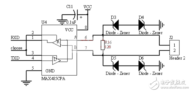
First, RS485 bus introduction The RS485 bus is a common serial bus standard that uses balanced transmit and differential receive, and therefore has the ability to reject common-mode interference. The RS485 bus is one of the most widely used buses when some communication distances are required from tens of meters to kilometers. And it also has a wide range of applications in multi-node work systems. Second, RS485 bus typical circuit introduction RS485 circuits can be generally divided into isolated and non-isolated types. The isolated type has better performance in terms of anti-jamming and system stability than the non-isolated type, but there are some occasions where non-isolated type can also be used. Let us first talk about the non-isolated typical circuit. The non-isolated circuit is very simple. Only one RS485 chip can be directly connected to the serial communication port of the MCU and an I/O control port. As shown in Figure 1: Figure 1, typical 485 communication circuit diagram (non-isolated) Of course, the above picture is not a complete 485 communication circuit diagram, we also need to add a 4.7K pull-up bias resistor on the A line; add a 4.7K pull-down bias resistor on the B line. The middle R16 is the matching resistor, which is generally 120Ω. Of course, this depends on the cable you use for transmission. (Matching resistance: 485 In the whole communication system, for the stability of the transmission of the system, we usually add matching resistors at the first node and the last node. So we usually set one at each node when designing. The 120Ω resistor of the jumper is set by the field personnel as far as it is used or not. Of course, how to distinguish the first node or the last node depends on the experts on the spot.) TVS we generally use 6.8V This, we will explain further later. Shenzhen Happybate Trading Co.,LTD , https://www.happybateprojector.com