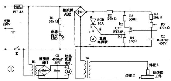
In the process of amateur electronics production and maintenance, it is inevitable to encounter welding battery pole pieces or thin steel plates, and to ensure the smooth completion of this task is inseparable from the welding machine. Electric welding machines can be generally divided into DC welding machines and AC welding machines. The AC welding machine is introduced here. It consists of a step-down transformer, a current regulator and a heat dissipation system, as well as welding wires and handles. It is not necessary to use the welding electrode when welding. It is only necessary to use the two workpieces to be welded as the two electrodes of the circuit, and use the high temperature generated at the contact resistance to melt the metal instantaneously, thereby firmly welding the workpiece together. Since the purchase of the finished electric welding machine is expensive, if you feel that your ability to do it is not too weak, you can also make full use of the DIY spirit to create a practical miniature AC welding machine. Circuit working principle As shown in Figure 1, B2 is a step-down transformer. It is also the core component of the welding machine. The AB2 rectifier bridge, the unidirectional thyristor SCR, the single junction transistor UJT, the resistors R2, R3, R4, R5, the capacitor C2 and the potentiometer RP constitute a welding current stepless regulator. The DC ammeter A is used to indirectly indicate the magnitude of the welding operating current. Just form a power indication circuit with the LED. The small transformer B1, the rectifier bridge AB1, the capacitor C1, and the fan M constitute a heat dissipation system. It can be seen from the figure that the device circuit is very simple. To be complicated, it can only be regarded as a current regulator. It uses the negative-impedance characteristics of a single-junction transistor to form a relaxation oscillator as a trigger circuit for a unidirectional thyristor. Since the power supply of the single-junction transistor relaxation oscillator is taken from the full-wave pulsating DC voltage output from the bridge rectifier circuit. When the thyristor is not turned on, the capacitor C2 of the relaxation oscillator is charged by R2, R5 and RP, and the voltage VC2 across the capacitor rises exponentially. When going to the peak-point voltage VP of a single junction transistor. The single junction transistor UJT is suddenly turned on, and the base region resistance RB1 is drastically reduced. Capacitor C2 is rapidly discharged to the resistor R4 through the PN junction, causing a positive transition of the voltage Vg across R4. A steep rising edge of the pulse is formed, and as the capacitor C2 discharges, VC2 decreases exponentially, and when it is lower than the valley voltage V, the single junction transistor is turned off. The output of the R4 is a cusp trigger pulse. The thyristor SCR is turned on. An alternating current flows through the primary winding of B2, and the voltage drop across the thyristor becomes small, forcing the relaxation oscillator to stop working. When the AC voltage crosses zero, the thyristor is forced to turn off. The relaxation oscillator is energized again, and the capacitor C2 starts to charge again, so that the above process is repeated over and over again. Adjusting the potentiometer RP can change the charging time of the capacitor C2, that is, changing the oscillation period of the relaxation oscillator. Naturally, the moment when the relaxation oscillator emits the first trigger pulse after each AC voltage zero crossing is changed. The conduction control angle of the thyristor SCR is changed accordingly, so that the voltage applied across the B2 primary winding changes. Finally, the purpose of regulating the secondary output current is adjusted. Device selection and testing The step-down transformer B2 selects the filament transformer of the end-of-life high-power amplifier tube FU-720F of the waste color TV transmitter. The primary AC voltage is 220V. The secondary AC voltage is 4 V. Stable output current up to 80A. If you can't find a suitable low-voltage and high-current transformer like this, you can also make it yourself. First, find a 220V AC power transformer with a power of more than 300W and remove the original secondary winding coil. Another copper cable of 0,5 cm2 or more is wound around the transformer by 6 to 10 åŒ to ensure that the output voltage is about 4V. The single-junction transistor is BT33F, and the unidirectional thyristor is CR10AM. Before the actual production, it is necessary to check the quality of the pin electrode. For single junction transistors. First, determine the emitter e, put the pointer multimeter resistance file in the RX 1k file, and use the two meter pens to measure the positive and negative resistances of any two electrodes are equal (about 2 ~ 1OkΩ), the two electrodes are B1 and b2, the remaining one electrode is the emitter e, then the first base b1 and the second base b2 are distinguished, the black meter is connected to the E pole, and the other two electrodes are sequentially contacted by the red test pen, respectively, and the positive direction is measured. resistance. Due to the construction of the tube, the second base b2 is close to the PN junction, so the forward resistance between the emitters e and b2 should be slightly smaller than the forward resistance between e and b1, ranging from a few to a few ten kΩ. Therefore, when the measured resistance is small, the electrode connected to the red test pen is b2. When the resistance is large, the red test pen is connected to b1. But even b1 and b2 are upside down. Under normal conditions, the tube will not be damaged. It only affects the amplitude of the output pulse; if the amplitude of the output pulse is found to be small. Simply swap the two bases together. The unidirectional thyristor looks like a high-power triode. When the anode (a), cathode (k) and gate (g) three-electrode pins are discriminated. To use the pointer type multimeter R × 10 file. The measured resistance is not connected to the other two feet (positive and negative resistance values ​​of several hundred kilo ohms or more) is the A pole. Then measure the remaining two feet of resistance. When the resistance is small (about tens or hundreds of ohms). The black test pen is connected to the g pole. The other foot is k pole. If the test results do not match the above situation. Indicates that the component is broken. The DC ammeter A can be replaced by an easy-to-buy milliampere meter followed by a long wire. The wire is equivalent to a small resistance shunt resistor. The specific length should be determined according to the actual use of the display situation. The cooling fan uses a common DC 12V computer fan, and the transformer B1 can take 10V. The resistor should be 2W or more, and the FU should be a 250V or 4A fuse. Considering that the secondary output current is large, the soldering lead wire should be made of copper core wire and have sufficient cross section to ensure that it will not be burnt due to overload during use. Finally, it should be noted that the circuit should be placed in a suitable metal casing after assembly. In addition to ensuring good ventilation, the entire circuit should be well insulated from the casing and the casing must be reliably grounded. Precautions for use Connect the three-pin plug to 220V mains and close the power switch K. The power indicator LED lights up. At the same time, the cooling fan starts to work, and the potentiometer RP knob is turned to adjust the proper welding current to perform the welding operation. Due to the limitation of welding current, the diameter of the metal workpiece cannot be greater than 3mm or the thickness is not more than 0.5mm. The workpiece should be kept stable during welding. A welding clamp can be used to fix one welding rod to one workpiece, and the other welding rod can contact another workpiece. After melting, disconnect a soldering electrode. In addition, it is also possible to punch a hole in a thin metal plate, or to clamp a metal workpiece with a welding pin, and use another welding electrode as a pen to engrave, draw, and the like on the workpiece. Operate the welder to understand and master the knowledge of safe electricity use. Part of the line with mains is insulated reliably. The welding wire is connected to the welding machine and the welding tongs, and the bolts and nuts are applied, and the gasket is tightened. The inside of the welding machine must also be inspected regularly, and the connection is found to be loose or desoldered, and should be tightened and welded in time. When the wire is broken, it should be replaced or treated in time; when the welding work is completed or suspended, the power should be cut off immediately. When moving the welding machine, the power must be cut off. Because there is a large amount of sparks during welding, the temperature of the weldment is extremely high. For safety reasons, keep away from inflammable and explosive materials during welding, and pay attention to rainproof in outdoor work; to reduce the strong ultraviolet radiation hazard generated during welding. Continuous working hours should not be too long, and try to wear protective clothing and gloves made of canvas. AC welding machine The AC welder is essentially a special step-down transformer. The 220V and 380V AC power is changed to low-voltage DC power, and the AC welding machine is an electric welder whose output power source is AC power. The welding transformer has its own characteristics, and the external characteristic is the characteristic that the voltage drops sharply after the welding rod is ignited. principle: The current and voltage are stepped down by the three-phase main transformer, rectified by the thyristor element, and the output current is controlled by changing the phase angle of the thyristor. The current signal is taken out from the shunt of the DC output of the rectifier as a current negative feedback signal. As the DC output current increases, the negative feedback also increases, the conduction angle of the thyristor decreases, and the output current voltage decreases, thereby obtaining a reduced external characteristic. . The thrust circuit is such that when the output terminal voltage is lower than 15V, the output current is increased, especially when the short circuit is formed, and the external characteristic of the outer drag is formed, so that the welding rod is not easily stuck. The arc-ignition circuit increases the given voltage for a short time each time the arc is started, so that the arc-ignition current is large and the arc is easy to start. It can be known from the above description that when the arc is arced, the circuit is in a short circuit state, the voltage drops sharply, and the current needs to be large; after the arc starts, the arc is stabilized. At this time, the solution of the electrode and the capacitor is still in a short-circuit transition state, and the voltage is still decreased. The current is still large; after the transition is completed, it is in a normal welding state, the voltage rises and the current drops.
For diifferent USB types, micro USB, mini USB, etc. The logo, color or shape can all made as customers' requirement. With more than ten years of experience and capabilities assisting our customers in various industry, ETOP would be confident to be your qualified AVL and reliable manufacturing partner.
Related Products:usb cable,micro usb cable,usb data cable.
Data Cable,Data Flexible Electrical Magnetic Cable,Usb Data Cable,Micro Usb Cable,USB Connector ETOP WIREHARNESS LIMITED , https://www.etopwireharness.com