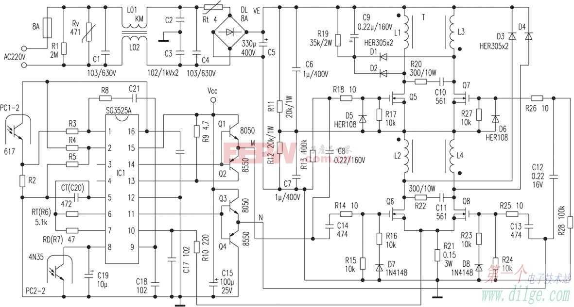
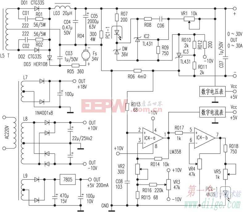
Common switching power supply circuits are single-ended (forward, flyback) and double-ended (push-pull, half-bridge, full-bridge). In order to improve the inverter efficiency, a power source with a large power is generally in the form of a double-ended circuit. In the double-ended circuit, the push-pull circuit is the simplest, and does not need to push the transformer. The disadvantage is that the voltage that the switch tube is subjected to is high, and there is also a problem of bias magnetism. Half-bridge and full-bridge circuits solve the shortcomings of push-pull circuits, but they must be used to push the transformer. After many years of practice, the author designed a series push-pull circuit. The main body of the circuit is like a bridge type, and the push circuit is like push-pull, which combines the advantages of both. From the application practice, the circuit is easy to manufacture and stable and reliable. An application example is described below, see two circuit diagrams respectively. IC1 (SG3525A) is a popular double-ended integrated voltage controller in recent years, operating at frequencies above 200kHz, in this case 35kHz. After power-on, the AC filters out interference, DL rectification, and C5 filter energy storage through C1, L01, L02, C2, C3, and C4, and supplies power to the inverter circuit. Rt is a negative temperature coefficient thermistor to reduce the current impact of the DL at the start-up instant. R11, R12 and R13, R28 are the equalizing resistors of C6 and C7. When the IC1{14} pin is high, the M point is also high, the pulse voltage is applied to the gate of Q6 via C14 and R14, and Q6 is turned on; the other side raises the potential of the positive terminal of C8 capacitor to make it The 1/2VE rises to 1/2VE+18V, is applied to the Q5 gate via R18, and Q5 is turned on. The primary coils L1 and L2 of the transformer B1 are simultaneously turned on, and the induced current of the secondary coil L5 is rectified and output by D01. Similarly, when the {11} pin is high, Q8 and Q7 are simultaneously turned on, the primary current flows through L3 and L4, and the secondary induced current is rectified and output through D02. Since Q6, L2, Q8, and L4 are alternately turned on in the lower 1/2 VE area, Q5, L1, Q7, and L3 are alternately turned on in the upper 1/2 VE area, which is equivalent to the use of two push-pull circuits in series, so the author calls it Series push-pull circuit. Although this circuit transformer has many primary windings, the production is slightly troublesome, but the switching tube is simple to drive and the protection circuit is simple and reliable, so it is suitable for small and medium batch production and amateur production. D5 and D6 provide charging paths for C8 and C12 respectively. D1, D2, C9 and R19 are the peak-voltage absorption protection circuits of Q5 and Q7, and D3 and D4 are the peak-pressure release paths of Q6 and Q8. PC1 and IC2 (TL431) form an output voltage detection circuit. In order to realize the adjustment from 0V, the IC3 negative voltage circuit is added. IC4 (LM358) and peripheral circuits and PC2, IC1 {8} also form a current detection and control circuit. By adjusting VR4 and changing the IC4 amplification factor, the output current can be kept constant at any value from 0 to 30A. When the output is short-circuited or overloaded, the primary current is first increased. The large voltage drop generated on R21 is sent to the IC1{10} pin via R10. The chip will turn off the output within 200ns, effectively protecting the components such as the switch tube from damage. . Then the current limiting circuit takes over and pulls the potential of the {8} pin through the PC2 secondary to limit the output current to the set value. D03, C03, and R05 provide power for the cooling fan Fs. The higher the output power, the higher the fan speed. The power supply transformer is a 5W transformer, which can be powered by a small switching power supply to reduce the size. The digital display meter power supply requires a regulated power supply. This machine is very practical in measuring power components. It only needs to connect diodes, triodes, FETs, IGBTs, thyristors and other components to the "+" and "-" output columns according to the polarity. To the large adjustment current button, the voltage drop corresponding to any current of the measured component can be synchronously viewed on the voltmeter and the ammeter, and the power component can be quickly measured, and even the operating current capability of the fuse and the metal wire can be turned on. Important parameters such as pressure drop are also easy to identify falsely labeled components. This circuit is especially suitable for making high power inverter power supplies. The author has designed 100A adjustable constant current source, 12~24V 500A electrolysis power supply and other products with satisfactory performance.
RJ45 Jack.China RJ45 Jack Crimping,RJ45 Jack Datasheet,RJ45 Connectors HSN Code,RJ45 Connectors 100 Pack Price, we offered that you can trust. Welcome to do business with us.
Antenk Modular Jacks are a complete line of PCB and wire leaded jacks which are UL and CSA approved and meet all required FCC rules and regulations. Antenk offers a multitude of sizes (4P2C thru 10P10C) with styles including single, ganged and stacked versions with options of ferrite or magnetic filtering and or metal shielding. Jacks with integral LED`s,These jacks are available in thru-hole or SMT mounting.
RJ45 interface can be used to connect RJ-45 connectors. It is suitable for the network constructed by twisted pair. This port is the most common port, which is generally provided by Ethernet hub. The number of hubs we usually talk about is the number of RJ-45 ports. RJ45 Jack Crimping,RJ45 Jack Datasheet,RJ45 Connectors HSN Code,RJ45 Connectors 100 Pack Price ShenZhen Antenk Electronics Co,Ltd , https://www.coincellholder.com

RJ45 is a type of different connectors (for example: RJ11 is also a type of connector, but it is used on the telephone); there are two different ways to arrange the RJ-45 connector: one is white orange, orange, white green, blue, white blue, green, white brown, brown; the other is white green, green, white orange, blue, white blue, orange, white brown, brown; therefore, there are also wires with RJ45 connector There are two kinds: straight line and interleaved line.
The RJ-45 port of the hub can be directly connected to terminal devices such as computers and network printers, and can also be connected with other hub equipment and routers such as switches and hubs. It should be noted that when connecting to different devices, the jumper method of twisted pair cable used is different.