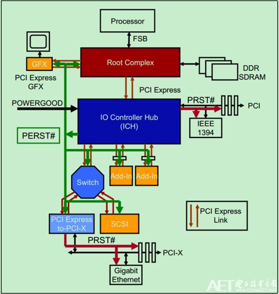
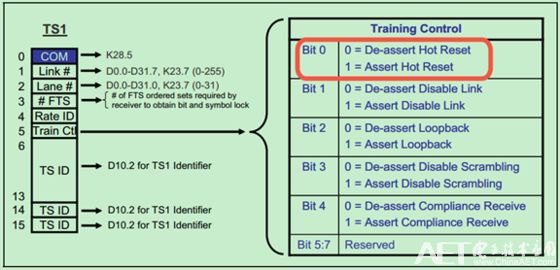
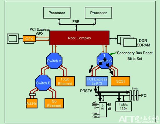
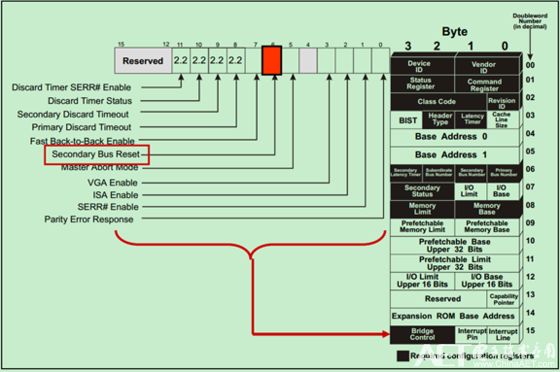
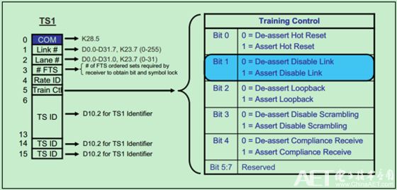
Four reset names are defined in the PCI bus: Cold Reset, Warm Reset, Hot Reset, and Function-Level Reset (FLR). Among them, FLR is a function added by PCIe Spec V2.0, so the other three resets are generally referred to as the traditional reset method (Conventional Reset). The cold reset and warm reset are based on the sideband signal PERST#, and are collectively referred to as the basic reset method (Fundamental Reset). The basic reset is handled automatically by the hardware, which resets the entire PCIe device, initializes all state machines and related hardware logic, port status, and configuration registers in the configuration space, etc. However, there is an exception, that is, the concept of Sticky (not affected by reset) was mentioned in the previous article about the PCIe error reporting mechanism. The premise that this is not affected by reset is that the power supply of the PCIe device has not been completely cut off. The function of Sticky helps the system locate errors and analyze the causes of errors. The cold reset in the basic reset refers to the reset caused by reconnecting after the main power supply is disconnected. It should be noted that even if the main power supply is disconnected, if the PCIe device still has auxiliary power supply Vaux to supply it, the reset will not affect the Sticky bits. PCIe Spec allows two ways to implement basic reset. One is to pass the sideband signal PERST# (PCI Express Reset) directly; instead of using the sideband signal PERST#, the PCIe device generates a reset signal by itself when the main power supply is cut off. A simple example is shown in the figure below: Warm Rest (Warm Rest) is optional and refers to the reset generated without turning off the main power supply. However, PCIe Spec does not clearly specify the mechanism of warm reset. Therefore, if a warm reset is generated, it is entirely up to the system designer to decide. Hot Reset is an in-band reset that does not use sideband signals. The PCIe device sends several TS1 Ordered Sets (where bit0 of the fifth character is 1) to the devices adjacent to its link, as shown in the figure below. These TS1OS are sent simultaneously on all lanes (Lane) and last for about 2ms. Note: For related content such as Ordered Set and LTSSM, please refer to the previous article on link initialization and training. The main point to note is that if the Upstream port of the Switch receives a warm reset, it will be broadcast to all Downstream ports and reset itself. If the Downstream port of the PCIe device receives a warm reset, it only needs to reset itself. When the PCIe device receives a hot reset, the LTSSM will enter the Recovery and Hot Reset state, then return to the Detect state, and restart the link initialization training. All state machines, hardware logic, port states and registers in the configuration space (except Sticky bits) of the PCIe device will be initialized to the default state. The software can generate a warm reset by writing 0 and then 1 to the secondary bus reset (Secondary Bus Reset) bit in the configuration space of the specific port of the bridge device, as shown in the following figure: It should be noted that if the software sets the secondary bus reset bit of the Upstream port of the Switch, the Switch will broadcast a warm reset signal to all its Downstream ports. The PCIe-to-PCI bridge will convert the received hot reset signal to PRST# and send it to the PCI device. The position of the Secondary Bus Reset bit in the configuration space is shown in the figure below: PCIe Spec also allows software to disable a link (Link) and force it to enter an electrical idle state (Electrical Idle). If a link is disabled, all downstream PCIe devices on the link will receive the link disable signal (via TS1OS, as shown in the figure below). PS Series Pluggable Connectors Ps Series Pluggable Connectors,Wire Connectors,Screw Terminal Block,Barrier Terminal Block Jiangmen Krealux Electrical Appliances Co.,Ltd. , https://www.krealux-online.com