Wireless Charging Multifunctional Sterilizer Phone Sterilizer,Mobile Phone Sterilizer Box,Wireless Charging Uv Sterilizer Box,Wireless Charging Multifunctional Sterilizer wzc , https://www.dg-wzc.com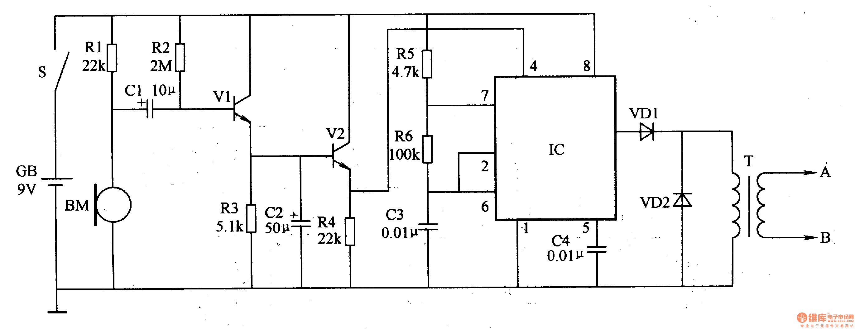
Circuit Operation The electronic snubber circuit consists of an audio detection circuit and a stimulus pulse generator circuit.
The audio detection amplifying circuit is composed of a microphone (microphone) BM, an audio amplifying tube V1, V2, capacitors C1, C2, and resistors R1-R4.
The stimulation pulse generator circuit is composed of a time base integrated circuit IC, resistors R5, R6, capacitors C3, C4, diodes VD1, VD2, and a pulse transformer T.
After the power switch S is turned on, the audio detection amplifying circuit of the electronic stop device is in a working state. At this time, if the user snoring, the microphone BM turns the hum into an electrical signal. After the electric signal is amplified by Vl and V2, it is applied to the 4th pin of the IC to make the stimulation pulse generator circuit work, and a pulse voltage is generated on the secondary winding of the pulse transformer T, and the pulse voltage is applied to the body of the player through the electrode. Parts (such as hands, feet, back, etc.), stimulate the snoring, make it change the sleeping position. After stopping the drive, the pulse voltage disappears.
Component selection
Rl-R6 uses 1/4W carbon film resistor or metal film resistor.
Both Cl and C2 use aluminum electrolytic capacitors with a withstand voltage of 16V; C3 and C4 use monolithic capacitors or polyester capacitors.
Both VDl and VD2 use 1N4007 silicon rectifier diodes.
Both Vl and V2 use S9013 silicon NPN transistors.
IC selects friends NE555 or 5G1555 type time base integrated circuit.
The BM uses an electret microphone (microphone).
T is made of E-shaped core: the primary winding is wound with 60-100 漆 of φO.18mm enameled wire, and the secondary winding is wound with 800-1000 漆 of φ0.09mm enameled wire.