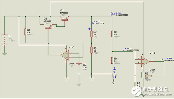
The system uses STC12C5A32S2 to realize the control part of the digital control power supply and the information acquisition part with its own 8-channel AD and 2-way PWM. P0 to P4 IO4 realize the data display part, which can be used as the digital control power supply and can be used. Digital clock and alarm clock can be displayed with digital tube or 1602 liquid crystal display. In fact, the STC12C5A32S2's 8-channel AD and 2-channel PWM can fully realize the fully automatic charging multi-function digital clock. The single-chip microcomputer can display the digital clock and charge the battery. The battery supplies power to the single-chip microcomputer. At the time, the system automatically recharged, but it was not completed due to hardware reasons, but it was an idea when the digital clock was improved. The part of the MCU is mainly used to control the operation of the system, collect the voltage and provide a reference voltage to the charger through the PWM, use the built-in AD to detect the voltage and current of the power supply, and the MCU controls the display of the 1602 liquid crystal to control the digital tube for the digital tube. Display, the control button switches each interface, the buzzer is used to implement the alarm, and the buzzer alarm is given when the alarm time is up. The display part is divided into two types, 1602 liquid crystal display and digital tube display, digital tube can display voltage value and current value, time, alarm clock. The button is used to switch the digital tube to display different interfaces. The hardware part of the system: First, the power (analog) part Figure 2 power supply simulation diagram Through this circuit, the power supply voltage is stabilized at 5V, and the reference point is 3.6V. When the output voltage is higher than 7.2V, the reverse voltage of U1:A will be higher than 3.6V. It will decrease, so that the output voltage is reduced. Conversely, when the output voltage is too small, the output voltage is increased. By adjusting the reference voltage, the power supply voltage can be varied. This system uses this principle to charge the battery. For current sampling, it is like a B3 battery. R4 is a relatively small resistor. It has little effect on the circuit. When the voltage across the resistor is sampled, the current flowing through the battery can be calculated by dividing the resistor. The voltage at both ends of the battery is sampled, using R7 and R8, and collecting the voltage U7 across R7, then u=U7/R7*(R7+R8). For current acquisition, the same direction proportional amplifier is used, and the sampling resistor is selected. It is 0.2 ohm. When the voltage is amplified five times, the voltage value just collected is equal to the value of the current, but the simulation and the actual circuit will be different. Shenzhen Esun Herb Co.,Ltd. , https://www.szyoutai-tech.com
