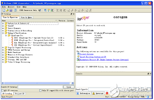
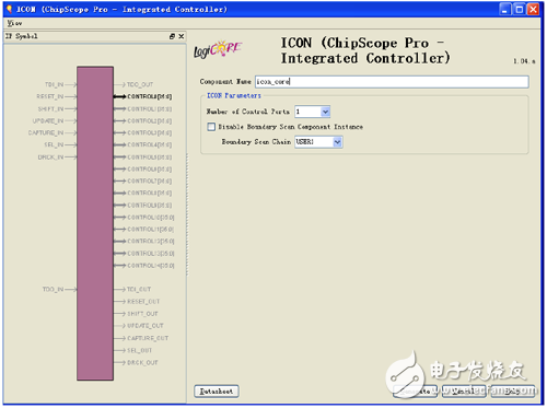
Xilinx offers different core generators for different types of debug IP cores. This section focuses on the ChipScope Pro debug IP cores ICON, ILA, VIO, and ATC2 supported by the Xilinx Core Generator Tool (see Figure 9-5). Figure 9-5 Debug IP core of Xilinx Core Generator Tool Double-click [Xilinx Core Generator] to open an existing IP core project or create a new IP core project. [View by funcTIon] → [Debug & VerificaTIon] → [ChipScope Pro], double-click ICON. The page shown in Figure 9-6 is displayed. Figure 9-6 ICON configuration interface (1) [Component Name]: Enter the component name. [Number of Control Ports]: ICON can connect up to 15 ILA, IBA, VIO and ATC2 cores. These kernels cannot share their control ports. [Disabling the Boundary Scan Component Instance]: This option is used to select whether to disable the boundary scan component inside ICON. By default, this item is unchecked, which automatically instantiates the boundary scan component inside ICON. A boundary scan primitive (eg, BSCAN_VIRTEX5) is used to implement communication with the JTAG boundary scan logic of the target FPGA. The Boundary Scan component extends the FPGA's JTAG Test Access Interface (TAP), which produces four scan chains, USER1, USER2, USER3, and USER4, through which ChipScope Analyzer communicates with the ChipScope core IP. Since these debug cores cannot use two scan chains in one boundary scan module at the same time, it is possible to share the same boundary scan module with other user logic. There are two ways to share the same boundary scan module: one is to instantiate the boundary scan module in ICON, and the unused boundary scan chain is output from ICON for other logic; the other method is in the design. In other places, the boundary scan module is instantiated, and the USER1 or USER2 scan chain is connected to the ICON core interface. Note: This option is only supported on Spartan-3, Spartan-3E, Spartan-3A and Spartan-3A DSPs. [SelecTIng the Boundary Scan Chain]: The ChipScope Analyzer analyzer communicates with the ChipScope core through a scan chain (USER1, USER2, USER3, or USER4). If the boundary scan module is instantiated in the ICON core, you can select a scan chain via the [SelecTIng the Boundary Scan Chain] drop-down list box. [Disabling JTAG Clock BUFG Insertion]: If the boundary scan module is instantiated in the ICON core, you can disable the insertion of BUFG in the JTAG clock chain. It is forbidden to insert BUFG, the JTAG clock will not use the global clock network, but the general wiring resources are used for wiring. The default is to automatically assign a BUFG. If you want to disable BUFG insertion, you need to set the kernel parameter "CSET enable_jtag_bufg=false" in the .XCO file. This option does not appear in the GUI interface. You need to manually edit the .XCO file after generating the kernel. Note: Consider putting the JTAG clock into the general purpose wiring only if the global resources are very scarce. Disabling the global clock buffer can cause timing problems or undesired behavior (such as "Found 0 cores in device" errors in the analysis tool). [Enabling Unused Boundary Scan Ports]: If the boundary scan component is instantiated in the ICON core, you can select the [Enabling Unused Boundary Scan Ports] check box to enable the unused scan chain USER* of the boundary scan component for other Logical use. The boundary scan primitives for Spartan-3, Spartan-3E, Spartan-3A, and Spartan-3A DSP devices have two sets of ports: USER1 and USER2. Note: This option is only supported on Spartan-3, Spartan-3E, Spartan-3A and Spartan-3A DSPs. In addition, this item is enabled only when using these USER* ports. If set to enable, but these ports are not used in the design, some synthesis tools may not produce the correct connection to ICON, or even generate errors during the synthesis or implementation phase. Mc4 Solar Connector,Mc4 Connect,Mc4 Branch Connector,Mc4 Y Connector Sowell Electric CO., LTD. , https://www.sowellsolar.com

(2) ICON Parameters.
The boundary scan primitives for Virtex-4/5/6 and Spartan-6 devices have four sets of ports: USER1, USER2, USER3, and USER4, but only one port is enabled at a time. These ports provide an interface to the TAP controller. The ICON core typically only communicates with one USER scan chain, so other unused ports can be used for other logic.
Xilinx Programmable Logic Device Design and Development (Basic) Serial 30: Spartan
9.2 ChipScope Pro Core Generator