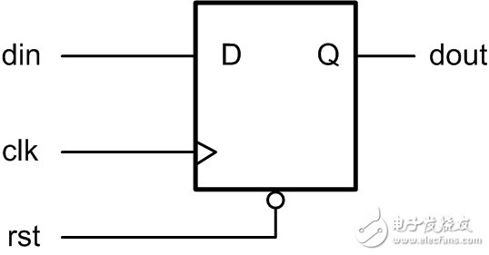
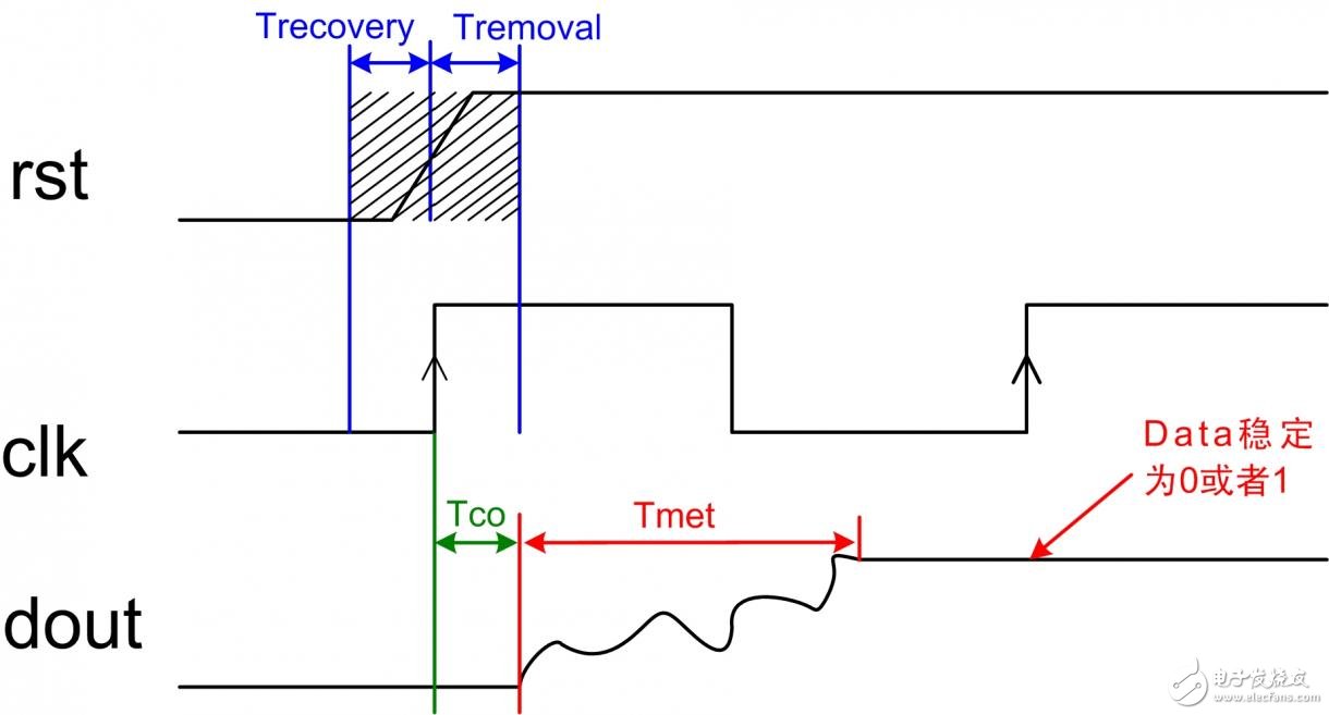
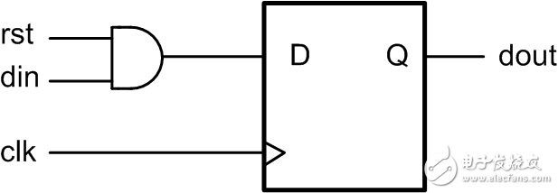
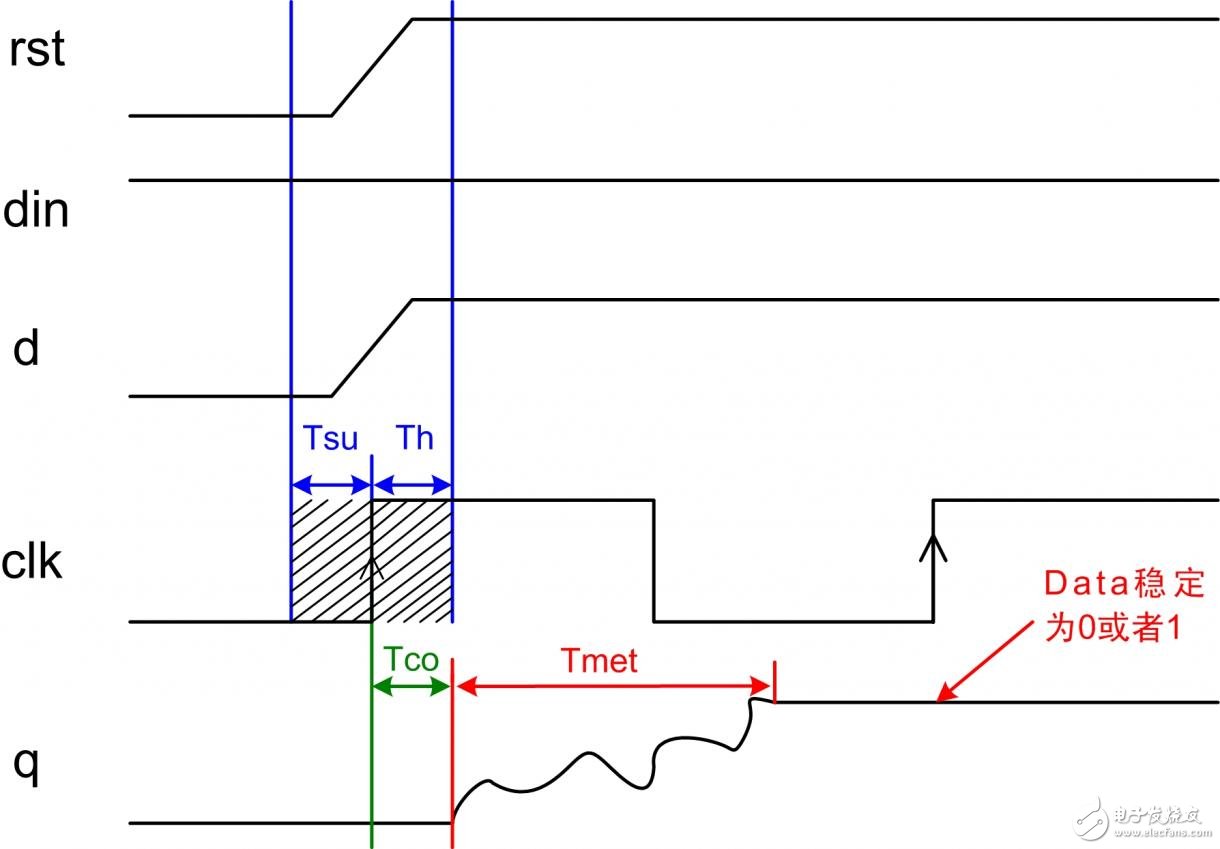
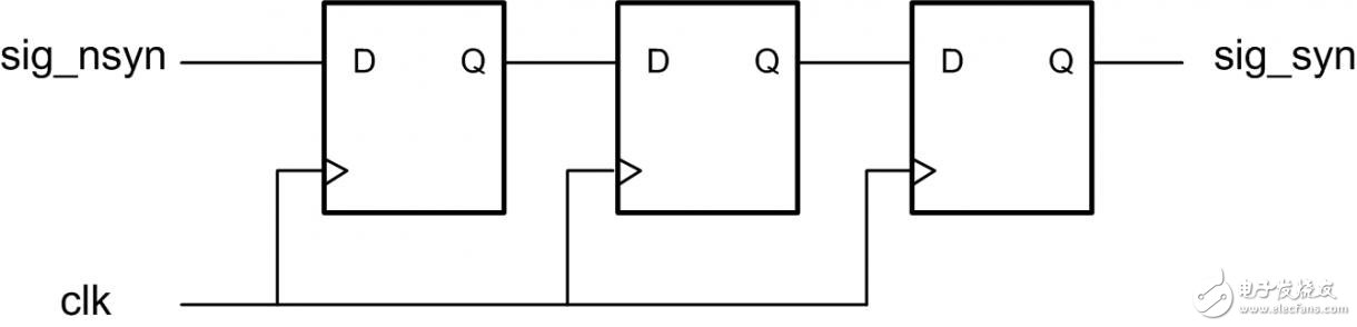
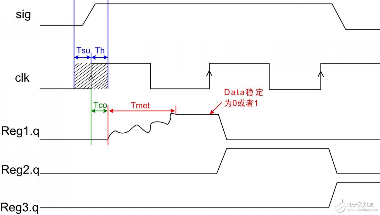
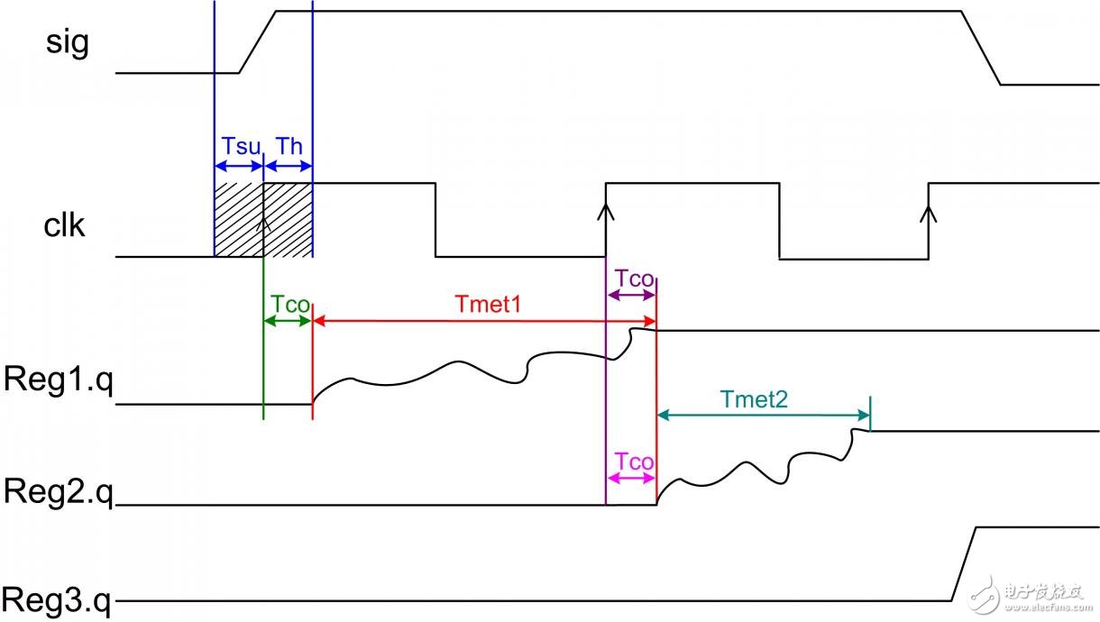
1.1 Causes of metastability In the FPGA system, if Tsu and Th that do not satisfy the trigger during data transmission are not satisfied, or the release of the reset signal during the reset process is not satisfied with respect to the recovery time of the effective clock edge (recovery TIme), metastable state may occur, At this time, the flip-flop output terminal Q is in an indeterminate state for a long period of time after the effective clock edge. During this time, the Q terminal is in an oscillating state between 0 and 1, instead of being equal to the value of the data input terminal D. This period of time is called the decision time (resoluTIon TIme). After the resoluTIon time, the Q terminal will stabilize to 0 or 1, but to 0 or 1, it is random and has no necessary relationship with the input. 1.2 Occurrence of metastable state As long as there are asynchronous components in the system, metastable state cannot be avoided. Metastable state mainly occurs in common designs such as asynchronous signal detection, signal transmission across clock domains, and reset circuits. 1.3 Metastable hazards After the metastable state is generated, the output of the Q terminal of the register may be a certain voltage value of glitches, oscillations, and fixed before it stabilizes. A metastable state in signal transmission will cause other connected digital components to make different judgments, some will reach "1", some will reach "0", and some will enter the metastable state. Will be confusing logic. A metastable state in the reset circuit may cause a reset failure. How to reduce the probability of metastable state has become an important consideration in FPGA design. 2.1 Metastable state in signal transmission In a synchronous system, the input signal is always synchronized by the system clock, which can meet the timing requirements of the register, so the metastable state will not occur. Metastable problems usually occur in some cross-domain signal transmission and asynchronous signal acquisition. The reasons for their occurrence are as follows: (1) During signal transmission across clock domains, since the phase shift between the source register clock and the destination register clock is unknown, the source register data sends out data, and the data may reach the destination register of the asynchronous clock domain at any time, so the destination register Tsu cannot be guaranteed. And Th requirements; (2) In the asynchronous signal collection, since the asynchronous signal can reach the destination register at any time, it cannot guarantee that the requirements of the destination register Tsu and Th can be met; When the data changes in the Tsu-Th time window of the destination register, that is, when the setup time or the hold time of the data is not satisfied, a metastable phenomenon may occur. As shown in Figure 3.1. Figure 3.1 Schematic diagram of metastable generation It can be seen from the figure that when the metastable state occurs after Tco time, there will be a Tmet (decision time) oscillation period. When the oscillation ends and returns to the stable state, it is "0" or "1". This is random. Therefore, it will affect subsequent circuit judgment. 2.2 Metastable state of the reset circuit 2.2.1 Asynchronous reset circuit In the design of the reset circuit, the reset signals are basically asynchronous, and the commonly used asynchronous reset circuit Verilog is described as follows: always @(posedge clk or negedge rst_n) begin if(!rst_n) a <<= 1'b0; else a "= b; end The integrated reset circuit model is shown in Figure 3.2: Figure 3.2 Asynchronous reset circuit model As shown in Figure 3.3, the reset timing diagram of the reset circuit. If the undo time of the asynchronous reset signal is within Trecovery (recovery time) and Tremoval (removal time), it will inevitably cause the generation of metastable state, and the output will oscillate after Tco of the clock edge, and the oscillation time is Tmet (decision time) ), eventually stable to "0" or "1", it may cause reset failure. Figure 3.3 Asynchronous reset timing 2.2.2 Metastable state of synchronous reset circuit In the reset circuit, because the reset signal is asynchronous, some designs use a synchronous reset circuit to reset, and most of the materials think that the synchronous reset circuit will not metastabilize, but in fact, the synchronous circuit will also generate sub Steady state, but the probability is less than asynchronous reset circuit. The verilog code below describes the synchronous reset circuit. always @(posedge clk) begin if(!rst_n) a <<= 1'b0; else a "= b; end The integrated hardware circuit is shown in Figure 3.4. Figure 3.4 Synchronous reset circuit Here, we will not discuss the resource consumption problem of synchronous reset, only discuss the metastable state of synchronous reset. When the input terminal Din is high and the reset signal's undo time is within clk's Tsu and Th, the metastable state is generated. As shown in the timing diagram in Figure 3.5, when the reset cancellation time is within Tsu and Th of clk, the input data is "1", and the data after the input data is also within Tsu and Th of clk, therefore, it will inevitably cause similar Metastable state of asynchronous signal acquisition. Figure 3.5 Timing diagram of synchronous reset circuit 2.3 Metastable state generation probability and crosstalk probability In actual FPGA circuit design, people often think about how to reduce the impact of metastability on the system. Few people consider how to reduce the probability of metastability and the probability of metastable crosstalk. 2.3.1 Probability of metastable state From the above analysis, it is known that the meta-stable state of the system occurs because the Tsu and Th of clk are not satisfied, or the removal and recovery time of the reset signal are not satisfied. For common FPGA devices, Tsu+Th is approximately equal to 1 ns, and the reset removal and recovery time is approximately equal to 1 ns. When the asynchronous signal is not a set of data, or the signal volume is small, it is necessary to perform synchronous processing on the asynchronous signal, for example, to collect an asynchronous pulse signal, as long as the pulse signal changes occur in the clock Tsu and Th window, it is likely Metastable state will be generated, the probability of metastable state is probably: Probability = (Setup Time + Hold Time)/Acquisition Clock Period (Equation 3-1) It can be seen from Equation 3-1 that as the frequency of clk increases, the probability of metastable state increases. For example, if the system uses a 100M clock to collect an external signal, the acquisition clock period is 10ns, and the probability of metastable state generated by the acquisition is: 1ns/10ns = 10% Similarly, a 300M clock is used to collect an external signal, and the probability of metastable state is: 1ns/3.3ns = 30% If a three-phase clock with a phase difference of 120° is used to collect an external signal, the probability of metastable state is close to 90% Therefore, in the process of asynchronous signal acquisition, to reduce the probability of metastable occurrence: (1) Reduce the system working clock and increase the system period, the metastable state probability will decrease; (2) Use FPGA with better technology, that is, FPGA device with shorter Tsu and Th time; 2.3.2 Probability of metastable crosstalk When using asynchronous signals, good design will synchronously process asynchronous signals. Synchronization generally uses multi-level D flip-flop cascade processing. As shown in Figure 3.6, three-level D flip-flops are used to process asynchronous signals synchronously. Figure 3.6 Three-level register synchronization Most of the information in this model is that after the first-level register generates a metastable state, the second-level register has a stable output probability of 90%, and the third-pole register has a stable output probability of 99%. If the metastable state follows the circuit all the time Pass it on, it will directly collapse another weak self-repair system. Next we analyze the probability of such crosstalk. As shown in Figure 3.7, a normal first-level register has a metastable state, and the second-level and third-level registers eliminate the metastable timing model. Figure 3.7 Tertiary register eliminates metastable state As can be seen from the above figure, when the metastable state of the first register occurs, after the oscillation of Tmet stabilizes, the second-level register can collect a stable value. But why might the second-level register still produce metastable state? Since the oscillation time Tmet is affected by many factors, the Tmet time is longer or shorter, so when the Tmet time is longer than one acquisition cycle, the second-level register will acquire the metastable state. As shown in Figure 3.8. Figure 3.8 Metastable state of secondary register It can be seen from the above figure that the second stage is also a metastable state, so in this case, the metastable state produces crosstalk, which is transferred from the first stage register to the second stage register, and may also crosstalk from the second stage register to The third level register. This will make the design logic judge wrong, and generate metastable transmission, which may cause the system to crash. 2.3.3 Metastable oscillation time Tmet The metastable oscillation time Tmet is related to the problem of the collection and stability of the subsequent register. The factors affecting Tmet include: the production process, temperature, environment of the device, and the time when the register is collected from the metastable state to the stable state. Even certain conditions, such as interference and radiation, can cause Tmet growth. If a metastable state occurs, we will eliminate the metastable state. There are three ways to eliminate the metastable state: (1) Synchronously process asynchronous signals; (2) Adopt FIFO to buffer data communication across clock domains; (3) Asynchronous reset and synchronous release methods are used for the reset circuit. 3.1.1 Synchronously extract edges for asynchronous signals In the process of asynchronous communication or cross-clock domain communication, the most commonly used method is to extract edges of asynchronous signals synchronously. Extracting the rising edge of an asynchronous signal is usually shown in Listing 4.1. Program Listing 4.1 Bipolar register extraction edge input sig_nsyn; wire sig_nsyn_p; reg[1:0] sig_nsyn_r; always @(posedge clk or negedge rst_n) begin if(!rst_n) sig_nsyn_r <<= 2'd0; else sig_nsyn_r "= {sig_nsyn_r [0], sig_nsyn }; end assign sig_nsyn_p = sig_nsyn_r [0] & ~sig_nsyn_r [1]; This edge extraction method is not suitable for a stable system. For example: when the first stage register acquires a metastable state, it will inevitably cause sig_nsyn_p to output a metastable state, which will cause a circuit that uses sig_nsyn_p to judge the signal. Affect, even judge the wrong value. According to the metastable state generation probability in section 3.3.1, if the first-stage register is planted at 100M, the probability of metastable state generation is about 10%. As the acquisition frequency of the system increases, the probability of metastable state generation is also Will rise with it. Therefore, when performing asynchronous signal cross-frequency extraction of edges, generally one more level of register is used to eliminate the metastable state. In the case of high system stability requirements, more levels of registers may be used to eliminate the metastable state, as shown in Listing 4.2 As shown, to eliminate metastable state using 4-level registers, the corresponding edge signal is generated two clock cycles later. Program Listing 4.2 Multi-level registers to extract edge signals input sig_nsyn; wire sig_nsyn_p; reg[3:0] sig_nsyn_r; always @(posedge clk or negedge rst_n) begin if(!rst_n) sig_nsyn_r <<= 2'd0; else sig_nsyn_r <<= {sig_nsyn_r [2::0], sig_nsyn }; end assign sig_nsyn_p = sig_nsyn_r [2] & ~sig_nsyn_r [3]; 3.1.2 FIFO for asynchronous cross-frequency data processing When the data flow goes from one clock domain to another clock domain, in most cases, FIFO is used as the intermediate buffer, and double clocks are used to buffer the data to avoid metastability. 3.1.3 Asynchronous reset, synchronous release For the metastable state under reset, it is often caused by the unsatisfactory recovery time and removal of the clock. Therefore, the most common processing method is to use asynchronous reset and synchronous release. Common circuit models are shown below. Use the second-level register output as the global reset signal output. Listing 4.3 Asynchronous reset processing wire sys_rst_n; reg [1:0] rst_r; always @(posedge clk or negedge rst_n) begin if (!rst_n) rst_r <<= 2'd0; else rst_r "= {rst_r [0], 1'b1}; end assign sys_rst_n = rst_r [1]; Through the above three ways to process asynchronous signals, asynchronous data, and asynchronous reset can effectively improve the stability of the system. Reduce the generation of metastable state.
HDG poles can be designed to encircle existing structures with ease and facilitate future expansion or retrofitting. HDG steel poles are self-conducting and thus have no need for a full-length copper grounding wire, and they can either be embedded or have an anchor base, and do not require fastener retightening due to pole shrinkage.
Yixing Futao Metal Structural Unit Co. Ltd. is com manded of Jiangsu Futao Group.
Steel Pole,Steel Light Pole,Steel Power Pole,Steel Tubular Pole,HDG Steel Pole YIXING FUTAO METAL STRUCTURAL UNIT CO.,LTD( YIXING HONGSHENGYUAN ELECTRIC POWER FACILITIES CO.,LTD.) , https://www.chinasteelpole.com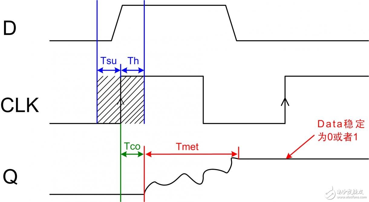
Three ways to reduce metastable state in FPGA system
1. Application Background
It is located in the beach of scenic and rich Taihu Yixing with good transport service.
The company is well equipped with advanced manufacturing facilities.
We own a large-sized numerical control hydraulic pressure folding machine with once folding length 16,000mm and the thickness 2-25mm.
We also equipped with a series of numerical control conveyor systems of flattening, cutting, folding and auto-welding, we could manufacture all kinds of steel poles and steel towers.
Our main products: high & medium mast lighting, road lighting, power poles, sight lamps, courtyard lamps, lawn lamps, traffic signal poles, monitor poles, microwave communication poles, etc. Our manufacturing process has been ISO9001 certified and we were honored with the title of the AAA grade certificate of goodwill"
Presently 95% of our products are far exported to Europe, America, Middle East, and Southeast Asia, and have enjoyed great reputation from our customers,
So we know the demand of different countries and different customers.
We are greatly honored to invite you to visit our factory and cheerfully look forward to cooperating with you.