Wire To Board Connectors,Electronic Connector,Connectors For Flat Cables,Underwater Sealing Connector Zooke Connectors Co., Ltd. , https://www.zooke.com Abstract: The power dissipated by an audio amplifier is mainly limited by its package form and external heat dissipation conditions (PCB copper foil or metal heat sink). However, more efficient amplifiers, such as Class D amplifiers, need to dissipate much less power than traditional Class AB amplifiers. Part of the power dissipation of all amplifiers appears as heat. This article discusses the power dissipation capabilities of the UCSP â„¢ package and how it limits output power relative to other packages.
UCSP packaging UCSP is a packaging technology that eliminates the traditional plastic packaging of sealed integrated circuits (ICs) and directly solders silicon to the PCB, saving PCB space. But it also sacrifices some of the advantages of traditional packaging, especially heat dissipation.
Most audio amplifier packages have an exposed pad, allowing the bottom layer of the IC to be directly connected to the heat sink or PCB ground plane. This design provides a low thermal resistance heat conduction channel from the IC to the surrounding environment to avoid overheating of the device.
With UCSP packaging, the IC is directly soldered to the PCB through the bottom solder ball, so a direct channel is formed from the bottom layer of the device to the PCB through the solder ball. These solder balls have low thermal resistance, but their area is much smaller than the typical exposed pad, resulting in reduced heat dissipation. Although non-grounded solder balls also contribute to heat dissipation, they are much lower than the heat dissipation capabilities of grounded solder balls. Most UCSP packaged chips have very limited system space, so it is not practical to use the top layer of the device to dissipate heat through the heat sink. Unlike other packages that use heat sinks, UCSP packages have a relatively rigid mechanical installation and are easily damaged when connected to heat sinks. The heat dissipation capability of the UCSP package should be considered in conjunction with the chip's grounded solder balls and ungrounded solder balls.
Power dissipation audio amplifiers generally provide multiple packages, and the maximum power dissipation depends on the package. In many cases, packaging limits the power dissipated, which in turn limits the possible output power.
Many ICs give the maximum continuous power that each package can dissipate in the maximum absolute ratings of their data sheets, as shown in Figure 1. Packages with exposed pads (such as TDFN) usually dissipate the most power. Note that the power dissipated in the UCSP package is much smaller than the exposed pad. 
Figure 1. Typical audio amplifier continuous power dissipation rating
Calculation of output power limit When we consider packages without exposed pads, we must realize that the form of the package reduces the power dissipation capability, and thus the output power. Using high-impedance loads can maximize efficiency and minimize losses.
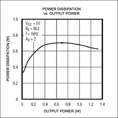
The output power that a Class AB amplifier amplifier can provide depends on the type of amplifier selected. Class AB amplifier manufacturers usually have a similar relationship between dissipated power and output power as shown in Figure 2. For an amplifier, it is also possible to provide the relationship curve under different input voltage and load impedance. 
Figure 2. Dissipated power and output power of a class AB amplifier
The continuous dissipated power from the absolute ratings (Figure 1) and the relationship between dissipated power and output power (Figure 2) are compared to determine the maximum output power that a given package can provide. In this example, the TDFN and µMAX® packages have no limit on the output power, while the UCSP package will limit the output power. Although the rated continuous power of the amplifier in the example is 1.1W, it can only output 100mW when using the UCSP package.
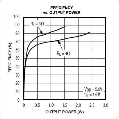
Class D amplifier Class D amplifiers generally replace the dissipated power curve with an efficiency curve, as shown in Figure 3. 
Figure 3. Correspondence between class D amplifier efficiency and output power
The efficiency of Class D amplifiers is much higher than that of Class AB, so the power dissipated at the same output power is much lower. The power dissipation can be calculated by the following formula: 
When obtaining a continuous output power of 1.1W, the amplifier needs to dissipate 225mW of power, which is lower than the maximum power dissipation of all packages shown in Figure 1, so for the same output power, various package forms can be used, including UCSP packages .
The audio source considers the output power calculation of the audio amplifier to generally use a 1kHz sine wave with 1% (<6W) or 10% (> 6W) THD + N. In practical applications, amplifiers are often used to restore speech, music or sound effects. These waveforms contain less energy than sine waves. Table 1 shows the RMS energy of several common sound source signals.
Table 1. RMS energy of a typical sound source Audio Source Material RaTIo of RMS Level to Peak Level (dB) Sine Wave -3 Rock Music -10.8 Telephone Ringing -12.3 Classical Music -15.8
These data show that to obtain the same output power, the output signal needs to have a higher peak voltage than the sine wave.
For example, the UCSP packaged AB amplifier mentioned above, if the peak value of the continuous output sine wave is 2.5VP-P, and it is replaced by the rock music in Table 1, even if the peak output voltage reaches 6.2VP-P, it will not exceed the allowable power dissipation capacity of the package . The sine wave with the same voltage peak can provide 600mW driving power for 8Ω load.
Conclusion The power dissipation capabilities of various packages must be considered when selecting an audio amplifier. In some cases, different packages can also obtain the same continuous output power. In fact, UCSP packages can allow less continuous power than packages with exposed pads. You can use high-efficiency class D amplifiers to replace class AB amplifiers to overcome power dissipation problems, rather than simply abandoning UCSP packaging. This design can make the application range of UCSP packaging wider.