Fast speed, simple and fast connection, no need for external power supply, good compatibility Dongguan Bofan technology Co., LTD , https://www.ufriendcc.com
(1) Thermal resistance two-wire transmitter This type of circuit includes: Pt100, Pt10, Cu50, Cu100, G, two-wire transmitter.
(2) Thermocouple Two-wire Transmitter This type of circuit includes thermocouple K, E, S, B, J, T, and WRE two-wire transmitters.
2, VB interface design of resistance calculation According to the requirements, for this interface, it should integrate the detection circuit type selection, resistance calculation, specific circuit diagram view, resistance resistance display (mixed circuit schematic) and other functions. When we select the desired detection circuit type, click OK. In the main window, we can display the resistances that need to be calculated. At the same time, in order to more clearly show the relationship between the resistances and the calculated In the position of the resistance in the circuit, we must also show the schematic diagram of the circuit and display the calculated resistance value in the corresponding position of the resistor on the schematic diagram. The view of the thermal resistance and thermocouple two-wire transmitter circuit in the main window is mainly to provide a comprehensive design circuit diagram for display on the desktop, while eliminating the effect of unclear circuit lines due to display resistance values. The main window of the interface is as follows: 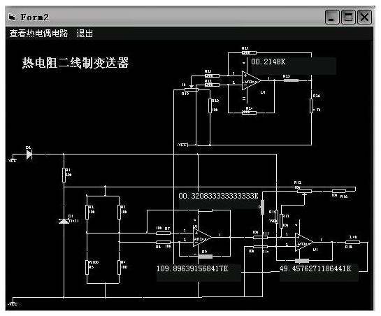 (1) Circuit type selection design In the type, we have various indexing two-wire transmitters. To do this, select the ComboBox command to create a drop-down selection menu, enter the desired type in the List ―list of the command, and then name the drop-down menu, such as CboOk. Also make the appropriate link in the main program. Some links are shown below:
If CboOk.Text="Please select the type" Then MsgBox "Must select the desired type"
If CboOk.Text="Pt100 (0~500 degrees)" Then...
Its function is mainly to select the required calculation through the control of the type.
(2) Resistor resistance display (mixed circuit schematic) design
A. For the display of the resistance value in the main window, you can use the TextBox command to display the calculated resistance value. Since you need to have the corresponding resistance symbol (R1 or other resistance symbol), use the Lable command to display the resistance value. The corresponding resistance symbol. In the calculation of the resistance, we can take the following approach (assuming the choice of Pt100 two-wire transmitter,
The formula for calculating a resistor R9 is known and the procedure for calculating R9 is as follows:
If CboOk.Text = "Pt100 (0-500 degrees)" Then
Label7(4).Visible = False
Label7(3).Visible = True
Text2.Text = (Val(Text1(0).Text) * 100 - 2.5 *2.809) / (2.5 * 0.1809)
Where Text2.Text represents the R9 we are asking for, and (Val(Text1(0).Text) represents our unknown value, or a value that is known to be taken into this formula.Label7(3)Visible, Label7 (4) Visible refers to the resistance values ​​of our third and fourth calculated outputs. In the thermistor transmitters, we specified them as kΩ, and in the thermocouple transmitter, we specify The unit is Euro, for which we need to hide the resistance in Ω when we need to display the resistance in kΩ.
B. For the circuit diagram displayed at the same time and the resistance value displayed in the circuit, we must create a new form Form2 and Form3, and also set a data transmission module to transmit the calculated resistance from Form1 to Form2 and Form3. The circuit schematic shows. To create a new form or module, you can select a new form or create a new module command in the project bar of the VB programming interface. In the module, we can set the variables arbitrarily, provided that they must be consistent with the variables in the Form1 main program.
The design idea of ​​C, Form2, Form3 is exactly the same, but when the thermal resistance circuit is displayed, the thermocouple circuit is not displayed. When the thermocouple circuit is displayed, the thermal resistance circuit is not displayed. This is where we need to use the Form2.Show Form3.Hide statement to block the display of Form3 or Form2. Since we have a separate circuit display, for this purpose, when only the circuit diagram needs to be viewed without the need to display the resistance value or the Lable box, several Lable display boxes in the circuit diagram also need to be masked.
In the illustration, we can select the type of circuit that needs to detect the temperature from the pull-down menu on the left and click OK. At this time, the background program is invoked to calculate and display the calculated resistance. There are two display methods. The first one is displayed on the main interface and can be displayed in the corresponding position of the resistance of the circuit schematic. In addition, we can view our required circuit schematic by clicking on the thermal resistance circuit and viewing the thermocouple circuit. Working examples are shown in the figure below. Second, the conclusion This article describes the thermal resistance, thermocouple two-wire transmitter with a simple circuit, low cost, high reliability, accuracy can be guaranteed within 0.5%. It can be made into a small-sized integrated two-wire transmitter and installed directly in the junction box of thermal resistance and thermocouple sensors. It has been mass-produced and has been widely used. At the same time, the auxiliary design software introduced in this paper solves the problem of difficulty in debugging due to the different circuit parameters of the transmitters with different indexing numbers and different ranges. Has a strong engineering practical value.
Temperature transmitter production debugging auxiliary computer software
First, the software design 1, design overview According to the needs of the actual design and production, for different ranges of different ranges of two-wire temperature transmitter, the circuit parameters are also slightly different, which brings inconvenience to the production of the product debugging, For this reason, an auxiliary software was designed to solve this problem based on the theoretical calculations. Here, the circuit principle of the same type of two-wire transmitter is basically similar, but there are several different resistance parameters. For this purpose, we can design an auxiliary calculation software to calculate the appropriate resistance value for different scale transmitter circuits with different index numbers. In the actual design process, we can be divided into two categories: