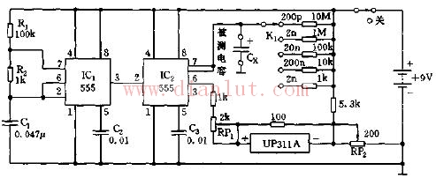
As shown, IC1 and R1, R2, and C1 form an astable multivibrator. Since R1 "R2", the duty cycle of the oscillation pulse is as high as 98%. It outputs the pulse waveform as the control wave of IC2. IC2 and the capacitor Cx to be tested and each range resistor constitute a controllable oscillator. Using the relationship i of the oscillation period proportional to the capacity of the Cx, the capacitance is converted to the corresponding voltage value and the digital reading is displayed on the digital panel meter. Shenzhen Jianjiantong Technology Co., Ltd. , https://www.jonsun-sz.com
