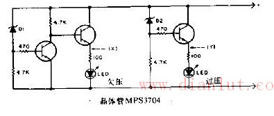
Over/undervoltage indicator circuit The figure shows the over/undervoltage indicator circuit diagram. In the circuit, if the monitored voltage value is higher or lower than the voltage determined by the Zener tubes D1 and D2, the circuit will cause the corresponding LED to illuminate to indicate that the voltage is abnormal. Rectifier bridge is to seal the rectifier tube in a shell. Points full bridge and half bridge. The full bridge connects the four diodes of the connected bridge rectifier circuit together. The half bridge is half of four diode bridge rectifiers, and two half bridges can be used to form a bridge rectifier circuit. One half bridge can also be used to form a full-wave rectifier circuit with a center-tapped transformer. Select a rectifier bridge to consider. Rectifier circuit and operating voltage. Bridge Rectifier,Original Bridge Rectifier,Full Bridge Rectifier ,Diodes Bridge Rectifier,Single Phase Rectifier Bridge, Three Phase Bridge Rectifier YANGZHOU POSITIONING TECH CO., LTD. , https://www.pst-thyristor.com