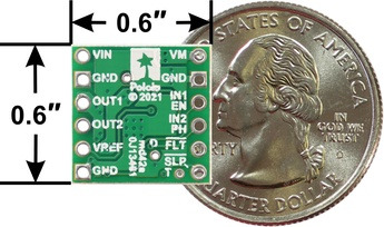
We’re pleased to announce our inaugural products based on the DRV8256E and DRV8256P motor drivers from Texas Instruments, which we are especially excited about. These little carrier boards can deliver a continuous 1.9 A to a single brushed DC motor at voltages from 4.5 V to 48 V, so they have some of the broadest operating ranges of any of our drivers, and they can handle short bursts of considerably higher current (up to 6.4 A for less than a second). They also feature configurable active current limiting, which can help make them good choices for a motor that might only draw around an amp when running but much more when starting.
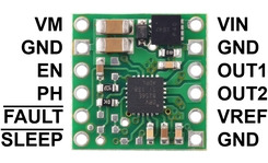
The DRV8256E and DRV8256P are very similar, and we use the same printed circuit board for both chips, but their control interfaces are different. The E version provides a phase/enable interface that lets you control a motor with a single PWM speed signal along with a simple digital direction signal, while the P version provides an IN/IN interface that gives you direct control over the motor outputs but requires two PWM signals for bidirectional speed control.
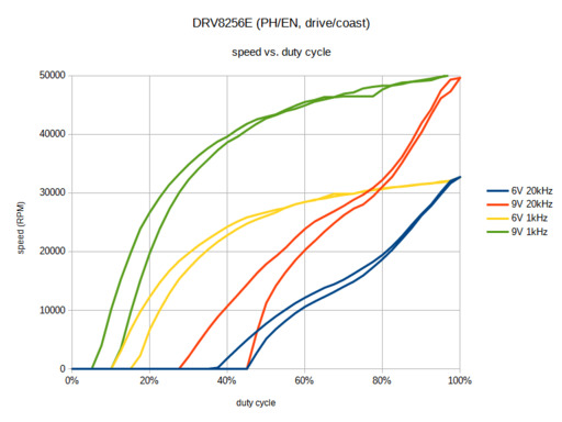
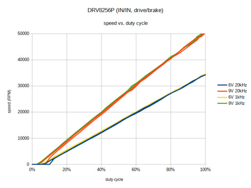
However, there is also a tradeoff with these two ICs. The DRV8256P uses drive/brake operation, shorting the motor outputs together and electrically braking the motor during the off portion. Many other TI drivers with phase/enable interfaces (like the DRV8838) also use drive/brake, but the DRV8256E does not: it operates in drive/coast mode, where the motor outputs are high impedance during the off portion of the PWM cycle, allowing the motors to coast. We don’t know why TI made a different decision for the DRV8256E, but it seems likely they have some high-volume customers who prefer it this way.
In our experience, drive/brake mode provides a much more linear relationship between PWM duty cycle and motor speed, so for an application where that is important, you might choose to accept the need for an additional PWM signal to get that improved linearity. These graphs show the difference in one specific scenario (powering a high-power micro metal gearmotor with no load):
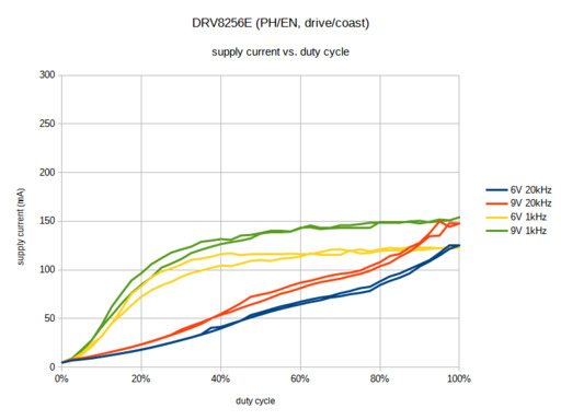
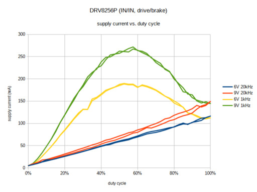
However, graphing the relationship between duty cycle and the current drawn by the motor driver from the supply reveals some more interesting differences. Specifically, at lower PWM frequencies, drive/brake operation uses much more current at intermediate duty cycles as the motor current ramps up and down for each PWM cycle:
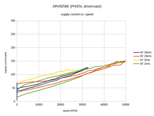
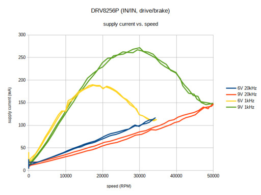
Finally, graphing current draw against motor speed shows that drive/coast can be more efficient for a given speed compared to drive/brake. So for an application with closed-loop speed control where it’s not as important for duty cycle to correspond linearly with speed, using drive/coast might be preferable if the PWM frequency is low.
If you have any thoughts about drive/brake vs. drive/coast and their use in different applications, we would be interested in hearing about it.
For more information about these drivers, see their product pages:
- DRV8256E Single Brushed DC Motor Driver Carrier
- DRV8256P Single Brushed DC Motor Driver Carrier
USB Connector
Usb Connector,Micro Usb Sinking Connector,Usb 3.0 Solder Connector,Double Layer Usb Connector
Dongguan Yangyue Metal Technology Co., Ltd , https://www.yyconnector.com